
NPT Size vs Measured Diameter Chart
A male OD near 0.840 inch is a strong clue for 1/2 NPT. A 14 TPI pitch-gauge reading makes the identification much stronger.
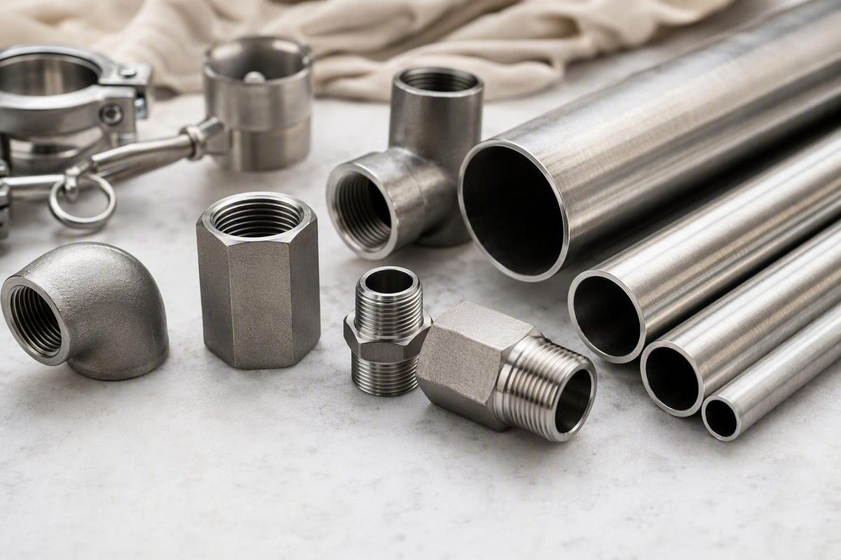
By the Tubing Chart editorial team · Updated August 20, 2026
The short answer: NPT size is nominal
An NPT size is a nominal pipe or trade designation, not the actual diameter measured across the threads. A male fitting labeled 1/2 NPT therefore measures substantially more than 1/2 inch: its commonly listed outside diameter is approximately 0.840 inch. NPT dimensions and thread form are governed by ANSI/ASME B1.20.1. For precision work, verify requirements against the current applicable edition rather than relying on a secondary chart alone. Engineers Edge summarizes the nominal sizing, governing standard, taper and common dimensions.
The nominal-size convention is historically related to pipe bore, but it should not be interpreted as the exact inside diameter of modern pipe. Actual bore varies with wall thickness. The nominal fraction is a standardized name used to specify compatible pipe and fitting sizes, not a direct caliper measurement.
A designation such as 1/2-14 NPT means:
- 1/2: nominal 1/2-inch pipe size
- 14: 14 threads per inch, or TPI
- NPT: American National Standard Taper Pipe Thread form
The essential identification rule is: confirm taper, then use measured diameter and TPI together rather than matching the nominal fraction directly to a caliper reading.
That two-value method matters because several NPT sizes share the same pitch. For example, both 1/2 NPT and 3/4 NPT use 14 TPI, so pitch alone cannot distinguish them.
NPT size chart: nominal size, male OD, TPI and pitch
The table below is intended for preliminary field identification of an external thread. The diameter column is the approximate male major outside diameter, not male minor diameter and not the accessible inside diameter of a female port. The OD and TPI pairs are supported by an NPT pipe-size reference chart, while a separate thread-form table explicitly identifies comparable values as major outside diameters. See the Fluidyne NPT pipe and port size chart.
Pitch is calculated as:
Pitch in inches = 1 ÷ TPI
Pitch in millimeters = 25.4 ÷ TPI
| Pitch family | Nominal NPT size | Approx. male major OD (in.) | TPI | Calculated pitch (in.) | Calculated pitch (mm) |
|---|---|---|---|---|---|
| 27 TPI | 1/16 NPT | 0.313 | 27 | 0.03704 | 0.941 |
| 27 TPI | 1/8 NPT | 0.405 | 27 | 0.03704 | 0.941 |
| 18 TPI | 1/4 NPT | 0.540 | 18 | 0.05556 | 1.411 |
| 18 TPI | 3/8 NPT | 0.675 | 18 | 0.05556 | 1.411 |
| 14 TPI | 1/2 NPT | 0.840 | 14 | 0.07143 | 1.814 |
| 14 TPI | 3/4 NPT | 1.050 | 14 | 0.07143 | 1.814 |
| 11.5 TPI | 1 NPT | 1.315 | 11.5 | 0.08696 | 2.208 |
| 11.5 TPI | 1 1/4 NPT | 1.660 | 11.5 | 0.08696 | 2.208 |
| 11.5 TPI | 1 1/2 NPT | 1.900 | 11.5 | 0.08696 | 2.208 |
| 11.5 TPI | 2 NPT | 2.375 | 11.5 | 0.08696 | 2.208 |
| 8 TPI | 2 1/2 NPT | 2.875 | 8 | 0.12500 | 3.175 |
| 8 TPI | 3 NPT | 3.500 | 8 | 0.12500 | 3.175 |
| 8 TPI | 3 1/2 NPT | 4.000 | 8 | 0.12500 | 3.175 |
| 8 TPI | 4 NPT | 4.500 | 8 | 0.12500 | 3.175 |
Field-identification note: These are approximate male major-OD lookup values, not dimensional tolerances or manufacturing acceptance limits. Because the thread is tapered, a caliper reading varies with axial measurement position. Coatings, wear, crest damage and technique can also affect the result. The major-diameter terminology and common NPT pitch families are shown in this NPT and BSP thread-form reference.
The bold rows cover common field sizes from 1/8 through 2 inches. The remaining rows are useful for larger threaded pipe and equipment connections, although other joining systems may also be encountered at larger sizes.
The pitch families illustrate why neither pitch nor diameter should be used alone:
- 1/16 and 1/8 NPT share 27 TPI.
- 1/4 and 3/8 NPT share 18 TPI.
- 1/2 and 3/4 NPT share 14 TPI.
- The listed sizes from 1 through 2 NPT share 11.5 TPI.
- The listed sizes from 2 1/2 through 4 NPT share 8 TPI.
A male OD near 0.840 inch is a strong clue for 1/2 NPT, but the identification is much stronger when a pitch gauge also shows 14 TPI. If it shows 18 TPI instead, the observations conflict; do not force the fitting into the nearest chart row.
No 5/8 NPT row appears in the main table. The supplied secondary references are inconsistent about that designation, so a component labeled 5/8 NPT should be checked against its product documentation and the governing specification rather than treated as a routine chart entry.
How to measure an unknown NPT thread
Basic field-identification tools include:
- Calipers for diameter
- A thread-pitch gauge for TPI
- Adequate light
- Magnification for difficult-to-see crests, roots or markings
- A cleaning brush or lint-free cloth for loose debris
The objective is to collect several clues that agree. One approximate diameter does not establish either the thread system or nominal size.
1. Identify the thread gender
A male thread is external and can be measured across its outside. A female thread is internal, inside a fitting or port.
Male NPT may be labeled MPT, MNPT, NPT(M) or MIP. Female NPT may be labeled FPT, FNPT, NPT(F) or FIP. Treat these markings as clues rather than substitutes for physical verification because terminology can vary among suppliers.
2. Clean and inspect the thread
Remove loose sealing tape, compound, dirt and corrosion before measuring. Do not scrape away intact plating or reshape the thread crests.
Inspect for:
- Flattened or rolled-over crests
- Burrs
- Cross-threading
- Paint or heavy plating
- Corrosion or galling
- Tool deformation
- Missing or incomplete lead threads
Choose a full, undamaged section for the preliminary measurement. If only a damaged section is accessible, record that limitation instead of treating the result as exact.
3. Check whether the thread is tapered
Measure the diameter at two documented axial positions. An NPT thread changes diameter along its length, whereas a straight or parallel NPS thread remains substantially constant apart from normal measurement variation and surface imperfections.
On a male NPT thread, diameter generally increases toward the fitting body. The accessible diameter of an internal thread changes in the corresponding direction inside the port.
Keep the calipers square to the thread axis.
4. Measure a male thread’s outside diameter
Place the caliper jaws across the crests of a full, undamaged portion of the external thread. Compare the result only with a table labeled male major OD.
Secondary guides do not establish one consistent field-measurement position. DirectMaterial recommends measuring near the base of a male thread, while other guides use different locations. Its illustrated guide shows the near-base approach.
Another manufacturer recommends measuring at the first full thread near the fitting end. Because NPT is tapered, these two locations can produce different caliper readings on the same component. RYCO documents the first-full-thread method.
For a repeatable preliminary result:
- Select a full, undamaged thread.
- Document its position relative to the fitting end.
- Measure across several pairs of crests.
- Rotate the component and repeat.
- Record the observed range.
- Compare that range with the chart as an approximation.
Do not compare a measured male major OD with a source that reports male minor OD. Those dimensions refer to different parts of the thread profile and do not have the same value.
5. Approach female threads cautiously
For a female port, measure the accessible internal thread diameter. Keep the caliper tips aligned and do not mistake a chamfer, counterbore or damaged entrance for the threaded diameter.
Female measurements are less dependable because:
- The reference position may be difficult to see.
- Caliper tips may not reach the intended thread surface.
- The entrance may include a chamfer.
- The first thread may be incomplete.
- A shoulder or adjacent component may obstruct access.
- A chart may report female major diameter, minor diameter or an informal opening measurement.
Treat an internal measurement as a preliminary clue. A known matching component and the equipment documentation may provide more evidence, but trial assembly must never involve forcing unlike threads together.
6. Determine the pitch
Seat a thread-pitch gauge against a clean, undamaged section. The correct leaf should align with the thread profile without visible gaps or rocking.
NPT pitch is normally expressed in threads per inch. If a gauge is unavailable, count thread intervals over the longest practical axial distance and divide by that distance. Avoid relying on only two or three damaged threads.
7. Compare diameter and TPI together
The final field comparison should answer three questions:
- Does the thread appear tapered?
- Which chart row is closest to the measured diameter?
- Does the measured TPI agree with that row?
If all three observations agree, the result is a likely identification. If diameter and pitch point to different rows, stop and investigate. Possible explanations include:
- Damaged thread crests
- Comparison with the wrong diameter type
- A straight rather than tapered thread
- BSP, metric or another thread system
- Paint, plating or another coating
- Incorrect pitch counting
- Deformation or an out-of-tolerance component
A near match is evidence to investigate, not permission to force two components together.
Worked examples and readings that fall between sizes
The most reliable way to understand nominal sizing is to work from the measured diameter, pitch and taper—not from the fraction in the name.
Example 1: 0.540-inch male OD and 18 TPI
Suppose a clean male thread measures approximately 0.540 inch, a pitch gauge shows 18 TPI, and measurements at two axial positions indicate taper. The likely designation is 1/4-18 NPT.
The 0.540-inch reading does not make it a nominal 1/2-inch connection. It is the approximate external diameter associated with the 1/4 NPT trade size. The nominal fraction and measured male OD are different quantities. These values are included in the published OD-and-TPI sizing table from PlumbingSupply.
Example 2: 0.840-inch male OD and 14 TPI
A tapered male thread measuring approximately 0.840 inch and matching a 14-TPI gauge is likely 1/2-14 NPT.
This is the standard illustration of why a literal fractional interpretation fails: the nominal size is 1/2 inch, but the commonly listed male major OD is about 0.840 inch.
Example 3: 1.315-inch male OD and 11.5 TPI
A tapered male thread measuring approximately 1.315 inches with a pitch of 11.5 TPI is likely 1-11.5 NPT.
Do not round the measured 1.315-inch diameter to a nominal 1 1/4-inch connection. The chart maps that approximate OD to 1 NPT; nominal 1 1/4 NPT is associated with an approximate male OD of 1.660 inches.
Why pitch alone is not enough
A 14-TPI reading leaves both 1/2 and 3/4 NPT as possibilities; their approximate male major ODs are 0.840 and 1.050 inches. Likewise, an 18-TPI reading could indicate 1/4 or 3/8 NPT, with approximate ODs of 0.540 and 0.675 inch. At 11.5 TPI, the chart includes four nominal sizes from 1 through 2 inches. Diameter is what separates rows within each pitch family.
What to do when the reading falls between rows
An in-between result does not automatically indicate an unusual NPT size. Check the likely measurement problems first:
- Clean the thread again. Remove loose tape, compound and debris between the crests.
- Check for paint or plating. Uneven coating can increase apparent OD.
- Inspect for wear. Flattened crests can reduce the reading.
- Look for deformation. Pliers, a vise or prior assembly may have made the thread oval.
- Check for burrs. One raised crest can make the calipers read high.
- Repeat at the same position. Do not compare readings from different axial positions without accounting for taper.
- Rotate the component. A meaningful change by orientation suggests damage, ovality or poor alignment.
- Verify TPI independently. Try adjacent pitch-gauge leaves rather than accepting the first close fit.
- Confirm taper. Do not identify a straight thread as NPT merely because its diameter and pitch resemble one row.
- Check labels and drawings. Product documentation may be more reliable than an obstructed field measurement.
Avoid shortcuts such as subtracting a fixed fraction from measured diameter to estimate nominal pipe size. The relationship is not a universal fixed offset, so such a rule is unsuitable for precision identification.
Escalate to a dedicated gauge or qualified inspection when the thread is inaccessible, heavily damaged, coated, still ambiguous or associated with controlled acceptance. Formal verification is also the conservative choice for high-pressure, hazardous-media or safety-critical service.
What defines the NPT thread form
Diameter and pitch identify a likely size, but they do not fully define NPT. The form also includes thread angle, taper, crest and root geometry, controlled diameters and engagement dimensions.
NPT uses a 60-degree included thread angle and a 1-in-16 diameter taper. That taper equals a 3/4-inch diameter change per foot of axial length. The taper-to-axis angle is approximately 1° 47′ 24″, or 1.7899°. These are diameter-taper values; “1 in 16” does not mean that the full diameter change occurs on one side of the thread. The NPT engineering reference provides these form and taper values.
Why taper affects assembly and measurement
As a tapered external thread advances into a corresponding internal thread, engagement becomes progressively tighter. Unlike a parallel screw thread, the diameter does not remain constant throughout the threaded length.
That has two practical consequences:
- Assembly resistance increases with engagement.
- Caliper diameter depends on axial position.
Two technicians can therefore measure the same undamaged fitting at different positions and obtain different values without either caliper being defective. For preliminary identification, document the measurement position and confirm the result with pitch and taper.
NPT size and pipe schedule are different variables
Pipe schedule describes wall thickness for a given nominal pipe size. Changing schedule changes wall thickness and available inside diameter, but it does not by itself change the standard pipe outside diameter or corresponding NPT thread profile for that nominal size.
Two pipes of the same nominal size can therefore have different bores while retaining the same nominal NPT connection size. Schedule still matters to mechanical design, flow and service suitability, but it is not a separate thread size.
NPT versus NPS, BSP and NPTF
Similar-looking threads are not necessarily compatible. Matching nominal labels or TPI values establish only part of the required geometry.
Use this compact decision path:
- Identify male or female thread gender.
- Check whether the thread is tapered or straight.
- Measure the appropriate diameter.
- Determine TPI.
- Inspect or verify the thread angle and profile.
- Consult the component specification and applicable standard.
Male NPT may be marked MPT, MNPT, NPT(M) or MIP; female NPT may be marked FPT, FNPT, NPT(F) or FIP. These labels are secondary clues, not proof of compatibility.
NPT versus NPS
NPT is tapered; NPS is straight or parallel. An NPS thread retains substantially the same diameter along its length, while an NPT thread changes diameter axially.
A shared nominal size does not make the sealing arrangements equivalent. Straight-thread systems may depend on a washer, gasket, O-ring, cone or another sealing feature rather than tapered-thread engagement. The component drawing must identify both the thread and intended seal.
“NPS” is also context-sensitive: it can refer to Nominal Pipe Size in piping discussions or a National Pipe Straight series in a thread designation. Read the complete designation.
NPT versus BSP
NPT uses a 60-degree thread form. BSP uses a 55-degree Whitworth-derived form with different crest and root geometry.
The distinction can be overlooked at nominal 1/2- and 3/4-inch sizes because NPT and BSP tables may both show 14 TPI. Matching pitch does not establish compatibility; angle, diameter, taper arrangement, profile and tolerances must also agree.
NPT and BSP are generally not interchangeable and should not be improvised together, especially in pressure service. Warning signs include an unexpectedly early bind, mismatched crest and root shapes, equipment intended for a BSP-using market, or documentation containing BSPP, BSPT, G, R, Rp or Rc terminology.
Unlike thread forms may begin to engage before their geometry interferes.
NPT versus NPTF
NPTF is a related tapered dry-seal form. It uses controlled truncation to establish root-and-crest contact in addition to flank contact.
That relationship does not make NPT and NPTF universally interchangeable. Verify:
- Exact thread designation
- Component specification
- Applicable standard
- Sealant requirements
- Fitting material
- Pressure and temperature
- Conveyed fluid
- Manufacturer instructions
- Inspection requirements
A manufacturer’s comparison of NPT, NPS and NPTF also shows why chart headings matter: some tables report male minor OD or female ID rather than the male major OD used in this article.
Sealing and tightening without unsafe rules of thumb
A conventional NPT joint ordinarily uses a suitable thread sealant rather than assuming tapered engagement alone guarantees a leak-tight connection. Sealant selection depends on:
- Fitting material
- Conveyed fluid or gas
- Pressure
- Temperature
- Thread condition
- Applicable procedure
- Manufacturer instructions
No single tape or compound is universally suitable for every metal, plastic, fluid and operating condition. Chemical compatibility, lubrication during assembly and the risk of contaminating the system must all be considered.
Sealant also changes assembly behavior. Material, wall thickness and thread condition add further variation, so there is no universal NPT torque value or mandatory wrench-turn count.
Some vendor guidance mentions finger-tight plus one or two wrench turns as a limited rule of thumb for certain tapered metal or plastic joints. It is not a manufacturing acceptance criterion or a universal installation instruction. The same guidance states that generic torque cannot be applied across all joints because material, sealant and wall thickness change assembly behavior. CPC explains these tightening variables and the limited rule of thumb.
Follow the fitting or equipment manufacturer’s procedure where one is provided. Controlled procedures may specify thread preparation, approved sealant, engagement, torque, inspection and leak testing.
Over-tightening is a particular concern with plastic or thin-wall components because additional engagement can damage threads or distort the connection. Use the manufacturer’s limits rather than treating the absence of an immediate visible crack or leak as evidence of correct assembly.
Keep thread identification separate from joint approval. A convincing chart match establishes only a likely nominal thread identity. It does not establish:
- Pressure rating
- Material or sealant compatibility
- Leak-free performance
- Adequate wall thickness
- Safe engagement
- Temperature capability
- Code compliance
- Suitability for hazardous service
Those questions require the specifications and installation requirements for the actual components and system.
Field identification versus standards-based inspection
Calipers and a pitch gauge answer the practical question, “What size is this thread likely to be?” They do not answer, “Does this manufactured thread conform to every applicable NPT limit?”
Conformance inspection may need to address:
- Pitch diameters
- Thread truncation
- Crest and root form
- Taper accuracy
- Lead
- Engagement dimensions
- Functional fit
- Permitted variation at the gauge plane
- Surface condition
- Product-specific requirements
Plug gauges for internal threads
An internal NPT thread is checked with the appropriate NPT plug gauge. The gauge is threaded carefully into the port without force, and its indicated position is evaluated under the gauge manufacturer’s instructions and controlling inspection procedure.
Ring gauges for external threads
An external NPT thread is checked with the appropriate NPT ring gauge. The ring is advanced without force, and its resulting position is evaluated under the applicable requirements.
A commercial NPT plug-and-ring gauging guide illustrates basic flush-position procedures. Its stated positions and limits should not be treated as universally controlling for every product, gauge design or standard edition.
When formal gauging is warranted
Use standards-based inspection rather than a chart-only match when:
- A field reading remains ambiguous.
- A female port is too deep or obstructed for reliable access.
- Threads are damaged, worn, plated, painted or coated.
- Components may use different national thread systems.
- A manufactured part is being accepted against a drawing.
- Incoming inspection has contractual consequences.
- The joint is intended for high-pressure or safety-critical service.
- Interchangeability must be demonstrated rather than assumed.
For precision manufacturing, incoming inspection and controlled service, use suitable calibrated plug or ring gauges and consult the current applicable edition of ANSI/ASME B1.20.1. Secondary charts may reproduce dimensions from older editions or omit tolerances, so they remain lookup aids rather than substitutes for the controlling standard.
NPT size FAQ
Why does a 1/2-inch NPT thread measure about 0.840 inch?
Because 1/2 NPT is a nominal trade size, not a statement that the external thread measures 0.500 inch. Its commonly listed male major OD is approximately 0.840 inch, and its pitch is 14 TPI. Identify it as 1/2-14 NPT only when diameter, pitch and tapered form agree. The published sizing table lists the 0.840-inch and 14-TPI pair.
Can two NPT sizes have the same threads per inch?
Yes. NPT sizes are arranged in repeated pitch families: 1/16 and 1/8 share 27 TPI; 1/4 and 3/8 share 18 TPI; 1/2 and 3/4 share 14 TPI; the listed sizes from 1 through 2 share 11.5 TPI; and the listed sizes from 2 1/2 through 4 share 8 TPI. That is why TPI must be combined with diameter and taper.
Does pipe schedule change the NPT fitting or thread size?
Not by itself. For a given nominal pipe size, changing schedule changes wall thickness and inside diameter while retaining the standard pipe outside diameter and corresponding thread profile. A thicker-wall pipe can therefore have a smaller bore without requiring a different nominal NPT connection.
Can NPT connect to BSP, NPS or NPTF?
Do not assume compatibility from nominal size or TPI alone.
- NPT and BSP: Generally not interchangeable because their angles and profiles differ, even where TPI matches.
- NPT and NPS: NPT is tapered; NPS is straight, and the intended sealing arrangements may differ.
- NPT and NPTF: Related tapered forms, but not universally interchangeable. Check the component specification, sealing requirements, material and service conditions.
Trial engagement is not an acceptance test.
How can I identify a female NPT port when caliper access is limited?
Use every available clue before relying on an uncertain internal measurement:
- Look for a cast, stamped or printed designation.
- Check the drawing, manual or bill of materials.
- Determine whether the port appears tapered or parallel.
- Clean the opening and identify any chamfer or incomplete lead thread.
- Measure the accessible internal diameter at a documented position.
- Determine TPI with a suitable internal pitch gauge or identification tool.
- Compare only with data for the same female diameter type and reference position.
- Confirm with the correct NPT plug gauge when accuracy matters.
Do not compare a female-port ID directly with this article’s male-major-OD column. If access remains poor, the thread is damaged or the result affects safe service or manufacturing acceptance, use formal gauging or qualified inspection.
The compact field workflow is: identify thread gender, confirm taper, clean the thread, measure diameter, determine TPI, and compare both observations with a correctly labeled chart. Nominal NPT size is not measured diameter, and repeated pitch families make single-value identification unreliable. Treat a field match as preliminary; ambiguous, manufactured, high-pressure or safety-critical connections call for the correct plug or ring gauge and the current applicable ANSI/ASME B1.20.1 requirements.