
How to Read a JIC Size Chart: Tube OD vs. Thread
-8 corresponds to 1/2-inch tube but uses a 3/4-16 thread. Match male OD or female ID with TPI, then verify straight threads and a 37° seat.
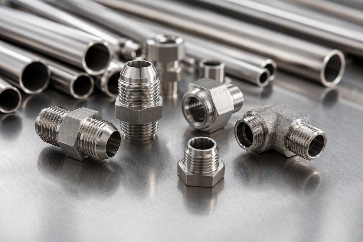
A JIC fitting cannot be identified from one diameter alone. The reliable method is to determine the fitting’s gender, measure its thread diameter and pitch, confirm that the threads are straight, and verify the 37° sealing seat. Only then should the measurements be mapped to the conventional tube-based dash size.
The chart below is a field-identification reference. It separates tube outside diameter from thread diameter—the distinction that prevents many sizing mistakes.
JIC fitting size chart: dash size, tube OD, thread and measured diameters
The conventional sizes and measurements below are corroborated across supplier charts. In particular, the dash-to-thread mappings and metric male and female measurements align with the JIC dimensional chart published by Tameson.
| JIC dash size | Nominal tube OD | Thread callout | TPI | Approx. male thread OD | Approx. female thread ID |
|---|---|---|---|---|---|
| -2 | 1/8 in | 5/16-24 | 24 | 0.3125 in / 7.9 mm | 0.26 in / 6.7 mm |
| -3 | 3/16 in | 3/8-24 | 24 | 0.375 in / 9.5 mm | 0.33 in / 8.3 mm |
| -4 | 1/4 in | 7/16-20 | 20 | 0.4375 in / 11.1 mm | 0.39 in / 9.9 mm |
| -5 | 5/16 in | 1/2-20 | 20 | 0.500 in / 12.7 mm | 0.45 in / 11.5 mm |
| -6 | 3/8 in | 9/16-18 | 18 | 0.5625 in / 14.3 mm | 0.50 in / 12.7 mm |
| -8 | 1/2 in | 3/4-16 | 16 | 0.750 in / 19.1 mm | 0.69 in / 17.5 mm |
| -10 | 5/8 in | 7/8-14 | 14 | 0.875 in / 22.2 mm | 0.81 in / 20.6 mm |
| -12 | 3/4 in | 1-1/16-12 | 12 | 1.0625 in / 27.0 mm | 0.97 in / 24.6 mm |
| -14 | 7/8 in | 1-3/16-12 | 12 | 1.1875 in / 30.2 mm | 1.11 in / 28.2 mm |
| -16 | 1 in | 1-5/16-12 | 12 | 1.3125 in / 33.3 mm | 1.24 in / 31.4 mm |
| -20 | 1-1/4 in | 1-5/8-12 | 12 | 1.625 in / 41.3 mm | 1.55 in / 39.3 mm |
| -24 | 1-1/2 in | 1-7/8-12 | 12 | 1.875 in / 47.6 mm | 1.80 in / 45.6 mm |
| -32 | 2 in | 2-1/2-12 | 12 | 2.500 in / 63.5 mm | 2.42 in / 61.5 mm |
How to read the chart: the thread callout combines nominal male-thread diameter and threads per inch. Thus, 3/4-16 means a nominal 3/4-inch thread with 16 threads per inch. It does not mean the fitting is intended for 3/4-inch tube.
The male OD and female ID columns are approximate caliper references for field identification—not SAE acceptance limits, thread-gauge limits, or manufacturing tolerances. Male OD is relatively straightforward because the caliper contacts the external thread crests. Female ID is more sensitive to the contact point within the internal thread. Supplier values can differ slightly because of rounding, thread geometry, plating, dirt, wear, damage, and measuring technique, as illustrated by the male and female measurements in Sinopulse’s JIC size overview.
This table intentionally covers only the common, consistently evidenced conventional sizes. It does not extrapolate rows for omitted numbers such as -7, -9, -11, -18, or -28. Their absence should not be interpreted as a universal statement about every proprietary catalog or historical product.
Editorial methodology: the table was assembled by comparing supplier charts for conventional dash size, tube OD, thread callout, TPI, and approximate caliper measurements. The underlying current SAE J514 and ISO 8434-2 texts were not independently reproduced or verified here. For final engineering, inspection, or procurement decisions, check the current applicable standard and the exact fitting manufacturer’s documentation.
What a JIC dash size actually means
A conventional JIC dash number represents the nominal tube outside diameter in sixteenths of an inch:
- -8: 8/16 inch, reduced to 1/2-inch tube OD
- -10: 10/16 inch, reduced to 5/8-inch tube OD
- -12: 12/16 inch, reduced to 3/4-inch tube OD
That tube-based convention is the key to reading a JIC size chart. Dash size does not directly state the thread’s measured diameter. A JIC -8 connection corresponds to 1/2-inch tube but uses a 3/4-16 thread. Similarly, JIC -6 corresponds to 3/8-inch tube while using a 9/16-18 thread.
Do not relabel a conventional JIC fitting according to thread diameter in sixteenths. A chart may call a 9/16-18 thread “-09” because 9/16 inch is its nominal thread diameter, but that is not the tube-based JIC convention used here. In this article, 9/16-18 is JIC -6 because the associated nominal tube OD is 6/16 inch, or 3/8 inch.
Dash notation must also be interpreted in context. Tube sizes generally refer to tube outside diameter, whereas hydraulic hose dash sizes generally refer to hose inside diameter. A fitting part number can contain one dash number for the connection end and another for the hose end. The MFCP explanation of hose, tube, and fitting dash notation illustrates this with a part number in which separate numbers identify the end connection and hose.
For example, a hose assembly described with a -8 JIC connection and -6 hose need not contain a contradiction:
- The -8 connection identifies the JIC end geometry.
- The -6 hose identifies the hose size in that product system.
- The position of each number in the manufacturer’s part number determines its meaning.
JIC refers here to a straight-thread, 37° flare connection associated with SAE J514. Because supplier literature uses inconsistent expansions of the acronym, the connection geometry and applicable specification are more reliable identifiers than an expanded name.
How a JIC connection seals
A JIC connection uses straight threads and matching 37° seating surfaces. The seal forms at the flare interface, not by interference between the threads. The threads draw the two sides together and mechanically retain the joint.
On a typical connection:
- A male JIC end has external straight threads and a visible 37° flare nose.
- A female JIC end has internal straight threads and a matching 37° seat.
- A female swivel has an internally threaded nut and a captive flare insert. The nut’s ability to rotate does not, by itself, identify the connection standard; the insert and its seat must also be examined.
- A flared tube assembly principally consists of the fitting body, flare nut, and sleeve.
When a male and female fitting are joined, the male flare contacts the female cone. In a tube assembly, the fitting body contacts the properly formed flare on the tube. Supplier descriptions of SAE J514 geometry likewise distinguish the flare-and-cone seal from the straight threads that mechanically hold the connection together in this SAE-thread JIC connection guide.
A simplified section view looks like this:
          FEMALE JIC END                     MALE JIC END

   internally threaded nut              external straight threads
       ┌───────────────┐                 / / / / / / / / /
       │  retaining    │◄──────────────►/ / / / / / / / /
       │   threads     │
       └──────┬────────┘
              │  female 37° seat       male 37° flare nose
│ /
│ \_______________/
              │          sealing line
              │      metal-to-metal contact
The illustration is conceptual rather than dimensional. Its important distinction is between the retaining threads and the sealing contact at the 37° surfaces.
Applying a thread product does not relocate the JIC sealing surface to the threads. If the flare or cone is incorrect or damaged, identify and correct the connection according to the applicable manufacturer’s procedure.
An adapter can have a JIC end on one side and a pipe-thread or another connection on the other. Any sealing instructions for that other end must be based on its own connection standard, not generalized from the JIC end.
How to measure and identify an unknown JIC fitting
Before loosening a hydraulic connection, isolate and depressurize the system according to the equipment manufacturer’s instructions and applicable workplace procedures. A supplier measurement guide likewise places depressurization, cleaning, and inspection before dimensional identification in its JIC measuring procedure.
Once removal is safe, clean the fitting so that dirt and residue do not alter the caliper or gauge contact.
Recommended tools
Use:
- Digital or dial calipers
- An inch-based thread-pitch gauge
- A 37° flare-angle gauge
- Adequate lighting and, if needed, magnification
A ruler can provide a rough estimate, but it is usually inadequate for separating close thread sizes or obtaining a useful female internal measurement. Do not rely solely on visual judgment to distinguish 37° from 45°.
Step 1: Determine the gender
A male end has external threads. A female end has internal threads.
Do not determine gender solely from whether a nut swivels. A female swivel normally includes an internally threaded nut and a captive seat insert. Inspect the threaded member and sealing insert rather than treating “swivel” as a separate gender.
Step 2: Measure the thread diameter
For a male thread, close the caliper jaws across opposite thread crests. Keep the jaws square to the fitting axis and record the largest consistent outside reading.
For a female thread, use the internal jaws to measure across the threaded opening. Compare that measurement only with the chart’s approximate female-ID column. Do not expect it to equal the nominal male-thread diameter.
Take several readings while rotating the fitting. A single reading can be distorted by burrs, flattened crests, dirt, damage, or an off-axis caliper.
Step 3: Identify the pitch
Place an inch thread-pitch gauge against the thread and find the blade that seats without visible gaps or rocking. Record the result in threads per inch.
Diameter and pitch must match the same chart row. A diameter that looks close to 3/4 inch is not enough to establish JIC -8; the pitch must also be 16 TPI.
For an internal thread, use a gauge designed for the available access. If the opening prevents a confident reading, obtain specialist identification rather than forcing a mating component into the thread as a test.
Step 4: Confirm straight threads
JIC uses straight, parallel threads. Inspect the thread form with an appropriate gauge or compare it with documented connection geometry. A clearly tapered thread is evidence against a JIC identification.
Minor caliper differences do not automatically prove taper. Thread crests, lead-in chamfers, wear, and measurement position can affect readings, so thread form must be considered together with pitch and seat geometry.
Step 5: Verify the 37° seat
Use a 37° angle gauge intended for fitting identification against the flare nose or female seating surface. Treat this as a field-identification check, not a substitute for standards-based dimensional inspection.
A 37° and 45° seat can look similar in a dirty, worn, or confined fitting. Some JIC and SAE 45° sizes also share thread dimensions, so a thread match combined with a visual angle estimate can still produce an incorrect identification.
Step 6: Inspect condition
Check the threads and sealing surface for:
- Dirt or embedded debris
- Corrosion
- Flattened or rolled thread crests
- Cross-threading
- Galling
- Dents or tool marks
- Cracks
- Distorted or uneven flare surfaces
- Plating buildup or loss
Damage can affect both identification and serviceability. A fitting may match a chart dimension yet remain unsuitable for assembly. Serviceability and reuse decisions require manufacturer-specific criteria.
Step 7: Identify every adapter end independently
Do not assume the other end of an adapter uses the same size or connection family. One end may be JIC -8 while the other is a different JIC size, ORB, NPT, BSPP, ORFS, or another form.
Record each end separately:
| End | Gender | Measured diameter | TPI | Straight/tapered | Seal or seat | Likely identification |
|---|---|---|---|---|---|---|
| A | Male/female | |||||
| B | Male/female |
A mating male and female of the same JIC size will not produce equal caliper readings. The male reading approaches the external major diameter. The female caliper contacts an internal part of the thread form and therefore produces a smaller number. That difference is expected, not evidence that the two sides have different nominal thread designations.
Worked JIC size lookups and borderline measurements
The easiest way to use the chart is to work from measured geometry toward a likely identification—not from a guessed dash number toward the measurements you hope to find. The following examples use the conventional tube and thread mappings also shown in a manufacturer’s JIC identification guide.
Example 1: About 0.56 inch and 18 TPI
Suppose a male fitting has:
- External straight threads
- An OD of about 0.56 inch
- 18 TPI
- A confirmed 37° flare nose
The likely nominal thread is 9/16-18. The corresponding conventional size is JIC -6, associated with 3/8-inch nominal tube OD.
The measured 0.56 inch is the thread-diameter reference. It does not make the connection “-9,” nor does it indicate 9/16-inch tube.
Example 2: About 0.75 inch and 16 TPI
A male straight thread measuring about 0.75 inch with 16 TPI and a verified 37° seat maps to:
- Thread: 3/4-16
- JIC size: -8
- Nominal tube OD: 1/2 inch
This is a common point of confusion: the thread is nominally 3/4 inch, but the JIC dash size describes 1/2-inch tube.
Example 3: About 1.06 inches and 12 TPI
A male connection measuring approximately 1.06 inches across the thread crests, with 12 TPI and a verified 37° seat, maps to:
- Thread: 1-1/16-12
- JIC size: -12
- Nominal tube OD: 3/4 inch
Do not reduce the 1.06-inch measurement to a nearby tube size. First identify the thread row; then read the tube-based dash size from that row.
Example 4: A female reading near 0.69 inch
A female JIC -8 connection may measure near 0.69 inch internally, even though its mating thread callout is 3/4-16.
That does not indicate an undersized 11/16-inch nominal thread. The measurement is being taken inside the female thread, not across the crests of an external 3/4-inch male thread. Compare it with the approximate female-ID reference, then verify 16 TPI and the 37° seat.
Reverse-lookup workflow
Use this sequence:
- Gender: male external thread or female internal thread?
- Measured diameter: male OD or female ID?
- Pitch: how many threads per inch?
- Likely chart row: which single row matches both diameter and TPI?
- Thread form: are the threads straight?
- Seat: is the sealing surface actually 37°?
Matching a row gives a candidate size; it does not, by itself, prove that the fitting is JIC. Straight-thread construction and the 37° seat must still be confirmed.
If the measurement falls between rows
Do not select whichever fitting starts onto the thread. Instead:
- Clean the fitting again.
- Repeat the measurement at several rotational positions.
- Confirm that the caliper is square to the fitting.
- Avoid measuring on the lead-in chamfer or a damaged first thread.
- Inspect for plating, corrosion, wear, or flattened crests.
- Recheck the TPI with a gauge.
- Verify straight rather than tapered construction.
- Gauge the seat angle.
- Consult the manufacturer or a qualified fitting specialist if the result remains ambiguous.
The chart establishes likely connection geometry only. It does not establish pressure rating, allowable temperature, material or fluid compatibility, assembly torque, vibration suitability, or whether a used fitting can be returned to service. Those decisions depend on the exact product and application.
JIC versus SAE 45°, ORB, NPT, BSPP and ORFS
Several connection types can resemble JIC from a distance or share one of its thread dimensions. The sealing geometry is the decisive second layer of identification. In particular, supplier references report that JIC and SAE 45° flare fittings share thread sizes at dash sizes 2, 3, 4, 5, 8, 10, 14, and 16, while warning that their different seat angles make them non-interchangeable (QC Hydraulics).
| Connection | Thread family | Straight or tapered? | Sealing surface | Main identifying feature | Assume direct JIC connection? |
|---|---|---|---|---|---|
| JIC 37° | UN/UNF | Straight | Matching 37° flare and cone | External flare nose or internal 37° seat | Only after size, pitch, thread form, and seat all match |
| SAE 45° flare | Unified threads in shared-thread sizes | Straight | 45° flare surfaces | Steeper 45° seat | No |
| ORB / UNO | UN/UNF-type O-ring-boss thread | Straight | O-ring compressed at the port | O-ring and boss geometry rather than a 37° mating flare | No |
| NPT | NPT pipe thread | Tapered | Thread engagement and interference | Visible or measurable taper; no JIC flare pair | No |
| BSPP | British Standard Pipe Parallel | Straight | Depends on the connection design | Different thread system and potentially a different seat or seal | No |
| ORFS | Straight thread | Straight | Flat face with an O-ring | Flat sealing face and O-ring groove | No |
JIC versus SAE 45° flare
JIC and SAE 45° flare connections can share thread dimensions, but their 37° and 45° seating surfaces do not match. A nut may thread on smoothly even though the flare angles are wrong.
Thread engagement confirms only that certain thread characteristics coincide. It does not establish a compatible sealing interface.
JIC versus ORB or UNO
ORB, also called O-ring boss in this context, can use a straight thread that looks compatible with JIC. Its sealing mechanism is different: the connection compresses an O-ring at the port instead of mating a male 37° flare with a female cone. Ryco’s comparison of JIC and UNO sealing methods distinguishes the common thread form from the different sealing arrangements.
Look for the O-ring position, boss geometry, and absence of the required JIC flare interface. Never treat a shared or similar thread as permission to substitute one sealing method for the other.
JIC versus NPT
JIC threads are straight; NPT threads are tapered. A clearly visible or measurable taper is evidence against a JIC identification.
Also inspect the end geometry. A JIC male has a defined 37° flare nose. An NPT connection does not become JIC merely because its diameter appears close to one chart row.
JIC versus BSPP
BSPP is a parallel-thread system, so the absence of taper does not prove JIC. Check the thread system, pitch, diameter, and actual sealing arrangement. A parallel thread with no matching 37° JIC seat must not be classified as JIC based on straightness alone.
JIC versus ORFS
An O-ring face seal connection is identified by its substantially flat sealing face and O-ring groove. JIC instead presents a 37° flare or cone. Even if the body size appears similar, the sealing faces distinguish the systems once they are cleaned and inspected.
The governing rule is simple: matching diameter and pitch are necessary, but insufficient. Identification also requires the correct thread form and sealing geometry.
JIC versus AN: shared geometry does not settle application compatibility
Supplier guides describe JIC and AN connections as sharing a 37° flare and nominal physical dimensions. That dimensional resemblance explains why the question of interchangeability arises.
The same sources distinguish their specifications, tolerances, thread forms or classes, and intended applications. One technical comparison describes JIC as using class 2A/2B UN/UNF threads and AN as using class 3A/3B UNJ/UNJF threads. It also associates the connection families with different specifications and application controls in its JIC-versus-AN comparison.
Neither absolute is justified:
- It is too broad to say that JIC and AN are universally interchangeable.
- It is also too broad to say that components described as JIC and AN can never mate dimensionally.
A dimensional match does not establish engineering approval. Before combining components, verify:
- The specification required by the equipment
- Thread series and fit class
- Material and finish
- Manufacturer approval
- Dimensional tolerances
- Traceability requirements
- Product-specific operating limits
- Any military, aerospace, or controlled-procurement requirements
Where an approved AN component is specified, substituting a dimensionally similar industrial JIC part may violate design, purchasing, or quality requirements even if the parts appear to assemble. Conversely, observed thread engagement does not prove that a mixed connection satisfies either specification.
Chart limits and final specification checks
This chart can identify a likely connection geometry:
- Conventional tube-based dash size
- Nominal thread callout
- Threads per inch
- Approximate male OD or female ID
- Straight-thread construction
- 37° JIC seat type
It does not establish:
- Exact SAE dimensional tolerances
- Acceptance or rejection gauge limits
- The formal status or availability of uncommon sizes
- Assembly torque
- Pressure or temperature rating
- Material or fluid compatibility
- Coating requirements
- Allowable vibration or fatigue conditions
- Inspection intervals
- Reuse criteria
- Application approval
Male and female caliper values should therefore be treated as field references, not pass/fail inspection limits. A measured fitting can be close enough to suggest a chart row while still requiring proper thread gauges, standards-based inspection, or manufacturer confirmation.
When a connection will be specified, purchased, assembled, or used in a safety-critical system, verify it against the current applicable SAE J514 or ISO 8434-2 specification and the documentation for the exact fitting. Manufacturer specifications should govern product-specific ratings, assembly procedures, and serviceability decisions.
The isolation and depressurization step in this checklist must be performed according to the equipment manufacturer’s instructions and applicable workplace procedures, consistent with the cited measurement-safety guidance:
- [ ] Isolate and depressurize the system before disassembly.
- [ ] Clean the fitting.
- [ ] Identify each adapter end independently.
- [ ] Determine male or female gender.
- [ ] Measure male OD or female ID with the correct caliper jaws.
- [ ] Measure TPI with an inch pitch gauge.
- [ ] Match diameter and TPI to the same chart row.
- [ ] Confirm that the thread is straight.
- [ ] Verify the 37° seat with an angle gauge.
- [ ] Inspect threads and sealing surfaces for damage.
- [ ] Confirm product-specific material, operating limits, torque, and application approval.
This article is general technical information, not evidence that Tubing Chart manufactures, sells, tests, certifies, or installs hydraulic fittings. Tubing Chart’s published terms likewise describe its material as general information provided as-is.
Frequently asked questions
What size thread is a -8 JIC fitting?
A conventional -8 JIC fitting uses a 3/4-16 thread: a nominal 3/4-inch thread diameter with 16 threads per inch. The -8 designation corresponds to 8/16 inch, or 1/2-inch nominal tube OD. It does not mean the thread is 1/2 inch (Sinopulse size chart).
For field identification, a male thread should measure approximately 0.750 inch or 19.1 mm across the external crests. A female internal reading may be near 0.69 inch or 17.5 mm. Confirm straight threads and a 37° seat before identifying the connection as JIC.
Why is a JIC -6 fitting threaded 9/16-18 if -6 means 3/8 inch?
The dash number and thread callout describe different features. The -6 means the connection is associated with 6/16-inch, or 3/8-inch, nominal tube OD. The mating thread callout for that conventional JIC size is 9/16-18 (TITAN Fluid identification chart).
The thread diameter is therefore not a restatement of the tube diameter, and the fitting should not be renamed according to the thread diameter in sixteenths.
Can a 37-degree JIC fitting connect to a 45-degree SAE flare fitting with the same thread?
No direct connection should be assumed. Some JIC and SAE 45° sizes share thread dimensions, so the nut may appear to fit, but the 37° and 45° seating surfaces do not match. The thread match does not create the correct flare seal (QC Hydraulics).
Identify the seat angle with a gauge and use components approved for the same connection standard. Thread sealant cannot correct mismatched flare angles.
Why does a female JIC thread measure smaller than the nominal thread size?
The nominal thread diameter is based on the external male thread’s major diameter. A caliper placed inside the female thread contacts an internal portion of the thread profile, so its reading is smaller.
For example, the nominal 3/4-16 thread used by JIC -8 can produce a female internal reading near 0.69 inch, or 17.5 mm. Compare female measurements with a female-specific reference, then verify TPI and seat geometry.
Does a JIC flare connection seal at the threads?
No. A JIC connection seals where the matching 37° metal surfaces contact: the male flare against a female cone, or the fitting body against properly flared tubing. The straight threads draw the surfaces together and mechanically retain the assembly (SAE-thread JIC connection guide).
Because the threads are not the JIC sealing interface, tape or liquid thread sealant cannot repair a damaged flare or make mismatched seats compatible.
The practical rule is to start with the chart, but never stop at diameter. A credible JIC identification requires the correct tube-based dash mapping, matching diameter and TPI, straight threads, and a verified 37° seat. If a measurement falls between rows or the sealing surface does not match, remeasure and consult the current standard or manufacturer documentation rather than forcing the connection.