
Pipe Weight Calculation for Empty and Filled Pipe
Verify actual OD and wall thickness, choose material density, calculate mass per length, then multiply by length and quantity and add fluid separately.
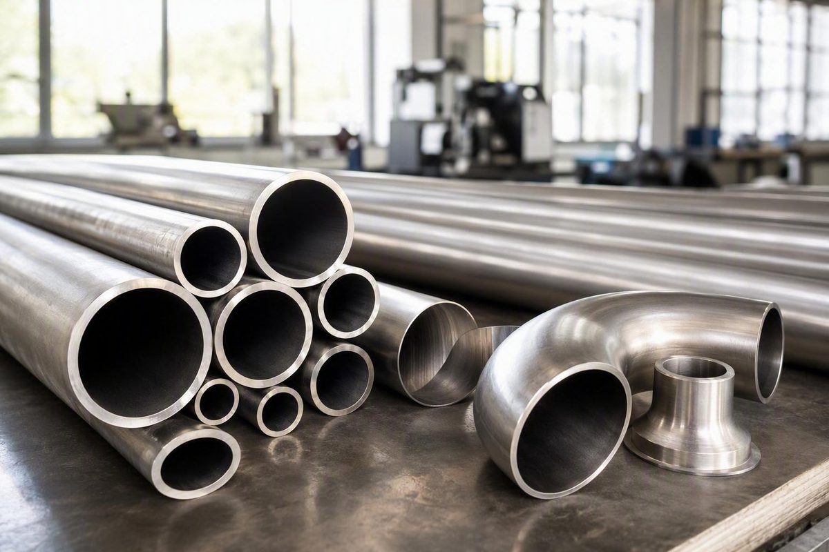
A reliable weight of pipe calculation begins with the pipe wall’s actual geometry—not its nominal size. Determine the outside diameter and either the inside diameter or wall thickness, calculate the annular cross-sectional area, multiply by the material density, and then multiply the resulting mass per unit length by pipe length and quantity.
This density-based method works for circular carbon-steel, stainless-steel, aluminum, copper, PVC, and other pipe. The familiar 10.69 and 0.02466 formulas are convenient carbon-steel shortcuts, but their constants incorporate specific density and unit assumptions. They should not be transferred unchanged to other materials.
The pipe-weight calculation at a glance
Use this sequence:
- Obtain the actual outside diameter.
- Obtain either the actual inside diameter or wall thickness.
- Select a density appropriate to the pipe material.
- Calculate mass per unit length.
- Multiply by pipe length and quantity.
- Add fluid, coatings, fittings, or other components separately when required.
The variables used throughout this guide are:
- OD = outside diameter
- ID = inside diameter
- t = wall thickness
- L = length of one pipe
- ρ = material density
- μ = pipe mass per unit length
- M = total pipe mass
- Q = quantity
For an ideal circular pipe, the exact mass per unit length is:
\mu = \rhoπ ÷ 4(OD²-ID²)
If only outside diameter and wall thickness are known:
ID = OD-2t
Substituting that relationship into the original formula gives an equivalent exact expression:
\mu = \rhoπ t(OD-t)
Total pipe mass is:
M = \mu LQ
These equations treat the pipe wall as a hollow cylinder. Pipe contents are calculated separately from the internal circular area, then added to the wall mass if an operating or filled mass is required. The empty- and filled-pipe relationships are summarized by the Engineering ToolBox pipe-weight equations.
Although industry charts commonly call kg/m and lb/ft “pipe weight,” those units describe mass per unit length. Force-weight requires gravitational acceleration.
Before calculating, make three input checks:
- Every dimension must be positive.
- ID must be smaller than OD.
- Wall thickness must be less than half the outside diameter for the object to remain a hollow pipe.
If t=OD/2, ID is zero and the object is a solid circular bar. If t>OD/2, the dimensions are physically inconsistent.
Why the formula works: hollow-cylinder volume multiplied by density
The formula follows directly from circular geometry.
The area enclosed by the pipe’s outside diameter is:
A_outside = π OD² ÷ 4
The area of the internal opening is:
A_inside = π ID² ÷ 4
Subtracting the opening from the outside circle gives the cross-sectional area occupied by pipe material:
A = π ÷ 4(OD²-ID²)
For a straight length L, pipe-wall volume is:
V = AL
Mass is volume multiplied by density:
M = V\rho
Therefore:
M = \rho Lπ ÷ 4(OD²-ID²)
Dividing by length gives mass per unit length:
\mu = M ÷ L = \rhoπ ÷ 4(OD²-ID²)
This derivation also makes the assumptions visible. The pipe is treated as a straight, uniformly circular hollow cylinder with consistent dimensions and material density along its length.
When wall thickness is known instead of ID, substitute ID=OD-2t:
A = π ÷ 4[OD²-(OD-2t)²]
Expand the squared term:
(OD-2t)² = OD²-4ODt + 4t²
Then:
A = π ÷ 4 [OD²-OD² + 4ODt-4t²]
A = π(ODt-t²)
A = π t(OD-t)
Thus:
\mu = \rhoπ t(OD-t)
This is exact for the stated ideal geometry. By contrast,
A ≈ π OD t
is a thin-wall approximation. It omits the -t^2 term and therefore gives a larger area than the exact expression. The difference can be small when wall thickness is very small relative to OD, but the exact formula is normally just as easy to use.
The geometry does not change with the material. Stainless-steel and aluminum pipes with identical OD and ID have identical wall areas and volumes, but different masses because their densities differ.
Pipe mass does not establish pressure capacity. The pressure formula and required material-strength input are distinct from the pipe-mass calculation, as illustrated by the separate weight and pressure tools in this pipe calculator reference. A schedule, chart mass, or calculated mass should not be treated as a pressure rating.
Unit-safe formulas for kilograms, pounds, kg/m, and lb/ft
Unit consistency is as important as geometry. Because the area term contains squared dimensions, a missed millimeter-to-meter conversion creates an error by a factor of one million in the area calculation.
SI base workflow
Use:
- OD, ID, and t in meters
- density \rho in kg/m³
- length L in meters
Then:
\mu_kg/m = \rhokg/m^₃ π ÷ 4 (OD_m²-ID_m²)
or:
\mu_kg/m = \rhokg/m^₃ π t_m(OD_m-t_m)
Total mass is:
M_kg = \mu_kg/mL_mQ
Practical millimeter workflow
Pipe dimensions are often supplied in millimeters. Convert each diameter or thickness to meters before using density in kg/m³:
OD_m = OD_mm ÷ 1000
ID_m = ID_mm ÷ 1000
t_m = t_mm ÷ 1000
Alternatively, account for the squared conversion directly:
\mu_kg/m = \rhokg/m^₃ π ÷ 4 (OD_mm²-ID_mm²) × 10⁻⁶
The equivalent OD-and-thickness form is:
\mu_kg/m = \rhokg/m^₃ π t_mm(OD_mm-t_mm) × 10⁻⁶
The factor 10⁻⁶ converts square millimeters to square meters.
Imperial workflow
Use:
- OD, ID, and t in inches
- density in lb/in³
Under the pound-mass convention commonly used in pipe references, the formula initially returns pounds per inch:
\mu_lb/in = \rholb/in^₃ π ÷ 4 (OD_in²-ID_in²)
or:
\mu_lb/in = \rholb/in^₃ π t_in(OD_in-t_in)
Multiply by 12 to convert lb/in to lb/ft:
\mu_lb/ft = 12\mu_lb/in
Then calculate total pounds using length in feet:
M_lb = \mu_lb/ftL_ftQ
A compact unit map is:
| Desired result | Diameter and thickness units | Density | Length used afterward |
|---|---|---|---|
| kg/m | m | kg/m³ | — |
| Total kg | m and a kg/m result | kg/m³ | m |
| kg/m from millimeters | mm with 10⁻⁶ area conversion | kg/m³ | — |
| lb/in | in | lb/in³ | — |
| lb/ft | in, then multiply lb/in by 12 | lb/in³ | — |
| Total lb | in with lb/in, or ft with lb/ft | lb/in³ | Matching in or ft |
Do not insert millimeter dimensions into the meter-based formula without converting them or applying the 10⁻⁶ area factor. Likewise, do not combine inch dimensions with a density stated in g/cm³ unless one set of units is converted first.
Exact conversion definitions commonly used in these calculations are 1 ft = 0.3048 m, 1 in = 25.4 mm, and 1 lb = 0.45359237 kg according to this steel-pipe calculation reference. From those definitions:
1 kg/m ≈ 0.672 lb/ft
This is a unit conversion, not a separate pipe-mass formula.
Mass and force should also remain distinct. In SI, force per unit length under standard gravity is:
w_N/m = \mu_kg/m × 9.80665
Thus, 10 kg/m corresponds to approximately 98.07 N/m under standard gravity. The 9.80665 multiplier and the distinction between kg/m and N/m are described in this pipe-weight calculation explanation; kilograms do not become newtons until acceleration is applied.
Carbon-steel shortcuts: when to use 10.69 and 0.02466
Two compact formulas appear frequently in carbon-steel pipe charts and estimating tools.
For carbon steel in imperial units:
\mu_lb/ft ≈ 10.69(OD_in-t_in)t_in
For carbon steel in metric units:
\mu_kg/m ≈ 0.02466(OD_mm-t_mm)t_mm
The dimensions and output units shown with each formula are mandatory. The constants cannot be separated from those units.
Both shortcuts come from the exact expression:
\mu = \rhoπ t(OD-t)
For the imperial calculation, the area is in square inches, density is in lb/in³, and a factor of 12 converts pounds per inch to pounds per foot:
\mu_lb/ft = 12π\rholb/in^₃ t_in(OD_in-t_in)
A commonly stated carbon-steel assumption is approximately 0.283 lb/in³. Under that assumption, 12π\rho rounds to about 10.67, while using a slightly higher rounded density produces a value nearer 10.71. The conventional shortcut rounds the coefficient to 10.69; this density basis and formula are stated in a carbon-steel pipe calculation guide.
The metric constant follows the same logic. With density equal to 7,850 kg/m³ and dimensions in millimeters:
\mu_kg/m = π(7,850)(10⁻⁶) t_mm(OD_mm-t_mm)
π × 7,850 × 10⁻⁶ ≈ 0.02466
The constant therefore combines annular geometry, an assumed density, and the square-millimeter-to-square-meter conversion.
Published reference densities and rounding conventions vary slightly. Consequently, two calculators can produce slightly different results even when their formulas and entered dimensions are otherwise consistent. Shortcut results also remain theoretical because they use specified dimensions, ideal circular geometry, and an assumed density.
For example, with:
- OD = 168.3 mm
- t = 7.11 mm
the metric shortcut gives:
\mu = 0.02466(168.3-7.11)(7.11)
\mu = 0.02466(161.19)(7.11)
\mu ≈ 28.26 kg/m
The same dimensions and approximately 28.26 kg/m result are given in the cited steel-pipe formula example.
Do not use either shortcut unchanged for stainless steel, aluminum, copper, PVC, or another material. Use the universal density-based formula with a density appropriate to the actual material.
Worked calculations in metric and imperial units
The following examples retain intermediate precision and round only the final reported values.
Metric example: 100 mm OD steel pipe
Given:
- OD = 100 mm
- t = 5 mm
- \rho = 7,850 kg/m³
- L = 6 m
- quantity = 1
First calculate ID:
ID = OD-2t
ID = 100-2(5) = 90 mm
Convert the diameters to meters:
OD = 0.100 m
ID = 0.090 m
Apply the annular formula:
\mu = 7,850 × π ÷ 4 × (0.100²-0.090²)
0.100²-0.090² = 0.010000-0.008100 = 0.001900
A = π ÷ 4(0.001900) ≈ 0.0014922565 m²
\mu = 7,850(0.0014922565) ≈ 11.7142 kg/m
Therefore:
\mu ≈ 11.71 kg/m
For a 6 m length:
M = 11.7142 × 6
M ≈ 70.26 kg
Cross-check with the exact OD-and-thickness form:
\mu = \rhoπ t(OD-t)
\mu = 7,850 × π × 0.005 × (0.100-0.005)
\mu = 7,850 × π × 0.005 × 0.095
\mu ≈ 11.7142 kg/m
Both exact forms agree. The density assumption is an approximate steel reference value rather than a universal grade-specific property; published material-density lists and calculators should be replaced with product-specific data when necessary.
Assumptions: ideal circular geometry, uniform wall thickness and density, and no coatings, linings, fittings, attachments, or contents.
Imperial example: thin-wall pipe
Given:
- OD = 3.000 in
- t = 0.022 in
- \rho = 0.284 lb/in³
- L = 12 in
- quantity = 1
Calculate ID:
ID = 3.000-2(0.022)
ID = 2.956 in
Calculate annular area:
A = π ÷ 4(3.000²-2.956²)
3.000² = 9.000000
2.956² = 8.737936
A = π ÷ 4(0.262064)
A ≈ 0.205824 in²
Mass per inch is:
\mu_lb/in = 0.284(0.205824)
\mu_lb/in ≈ 0.058454
For a 12 in length:
M = 0.058454 × 12
M ≈ 0.702 lb
The approximately 0.702 lb result for these inputs is also reported by the NASPD imperial and metric pipe-weight calculator.
The exact OD-and-thickness cross-check is:
A = π t(OD-t)
A = π(0.022)(3.000-0.022)
A = π(0.022)(2.978) ≈ 0.205824 in²
The two methods again agree.
Assumptions: ideal circular geometry, uniform wall thickness and density, and no coatings, attachments, fittings, or contents.
For multiple identical pipes, multiply the single-pipe result by quantity. For example, 20 pipes matching the metric example have a theoretical dry mass of:
M_batch = 70.26 × 20
M_batch ≈ 1,405.2 kg
This quantity extension follows the same density-times-volume method and multiplication by pipe quantity described by the general pipe-weight calculator and formula.
If lengths differ, calculate each group separately and add the totals rather than applying one length to the entire order.
Material density: calculating stainless steel and other non-carbon-steel pipe
Pipe geometry is material-independent, but calculated mass changes directly with density. For identical dimensions:
M₁ ÷ M₂ = \rho₁ ÷ \rho₂
The same relationship applies to mass per unit length. If the selected density is 10% higher, the calculated theoretical pipe mass is 10% higher when OD, ID, and length remain unchanged.
Approximate average reference densities include:
| Material | Approximate density |
|---|---|
| PVC | 1.45 g/cm³ or 1,450 kg/m³ |
| Aluminum | 2.70 g/cm³ or 2,700 kg/m³ |
| Carbon steel | 7.84 g/cm³ or 7,840 kg/m³ |
| Stainless steel | 8.03 g/cm³ or 8,030 kg/m³ |
| Copper | 8.96 g/cm³ or 8,960 kg/m³ |
These are average reference values from the Omni Calculator material-density list, not exact values for every grade, formulation, batch, or temperature.
Some calculation references instead use rounded assumptions such as 7,850 kg/m³ for steel and 8,000 kg/m³ for stainless steel. These are calculation inputs, not universal material properties.
For a rough comparison, suppose a carbon-steel pipe calculated with 7,840 kg/m³ has a mass of 20 kg/m. An identically dimensioned stainless pipe estimated at 8,030 kg/m³ would have:
\mu_stainless = 20 × 8,030 ÷ 7,840
\mu_stainless ≈ 20.48 kg/m
This proportional method is convenient when geometry is unchanged, but it is only as reliable as the selected densities.
Use a grade-specific or manufacturer-provided density when the distinction could materially affect procurement quantities, freight planning, lifting assessment, installed loads, or structural work. For a traceable calculation, record the material grade, density value, source, and assumed temperature rather than entering “steel” or “plastic” without qualification.
Nominal pipe size, schedule, and actual dimensions
Nominal pipe size is a designation, not necessarily a measured outside diameter. It should not be entered as OD without checking the applicable dimensional reference.
For example, nominal 4-inch Schedule 40 steel pipe is listed with:
- actual OD = 4.500 in
- wall thickness = 0.237 in
- theoretical mass near 10.8 lb/ft
These dimensions and theoretical mass appear in a Schedule 40 pipe-weight illustration. Entering 4.000 in instead of 4.500 in as OD would materially understate the annular area and calculated mass.
Schedule is not a wall thickness by itself. It is a wall-thickness designation that must be paired with nominal size and the applicable product standard or a verified product table. “Schedule 40” alone is therefore incomplete input.
At a high level, several sizing conventions may be encountered:
- NPS/IPS products can use outside diameters associated with iron-pipe sizing rather than a measured diameter equal to the nominal number.
- CTS products can define actual OD through a specified relationship to nominal tubing size.
- Metric products may follow different nominal or actual-diameter conventions.
The Plastic Pipe Institute calculator, for example, explains that its CTS, IPS, and metric selections use dimensions associated with listed product standards and assume nominal average OD and average wall thickness rather than treating every nominal label as a measured diameter. It also advises professional or manufacturer review rather than relying on calculator output alone for consequential applications, as stated in its pipe weight and volume calculator guidance.
ISO 4200, EN 10220, ASME B36.10M, and ASTM A53/A53M are commonly cited dimensional and weight references for carbon-steel pipe. This does not mean a secondary supplier table is a substitute for the governing current edition. A supplier’s pipe-weight and schedule summary also distinguishes plain-end data from threaded-and-coupled data, whose listed masses may differ.
Record at least:
- nominal size and sizing system;
- actual specified OD;
- actual specified wall thickness;
- product material and grade;
- schedule or wall designation;
- governing product standard and edition, if applicable;
- plain-end, threaded, coupled, or other end finish;
- manufacturer or table source;
- units and rounding convention.
Prefer the applicable licensed standard or certified manufacturer documentation when the calculation concerns standardized commercial pipe, a purchase order, or any case in which supplied product specifications govern. Use the geometric formula as a transparent cross-check or for custom dimensions. If the calculated value and controlled product data disagree meaningfully, investigate the dimensions, density, end condition, and included components rather than ignoring the discrepancy.
Filled pipe, added components, and real-world accuracy
Dry pipe mass includes only the material in the pipe wall. It does not automatically include liquid, gas, slurry, cable, insulation, coatings, flanges, or other system components.
For a completely full pipe, the internal cross-sectional area is:
A_internal = π ID² ÷ 4
Fluid mass per unit length is:
\mu_fluid = \rho_fluid π ID² ÷ 4
Add that result to the dry pipe-wall mass:
\mu_total = \mu_pipe + \mu_fluid
Combining the two terms gives:
\mu_total = π ÷ 4 [ \rho_material(OD²-ID²) + \rho_fluidID² ]
This formula assumes a completely filled, straight, circular pipe with uniform ID and representative material and fluid densities. Diameter and density units must be compatible.
As an illustration, an SI calculation for 4-inch Schedule 40 steel pipe reports approximately 16 kg/m for the empty pipe, 8.2 kg/m for the water, and 24.2 kg/m combined in the Engineering ToolBox filled-pipe example. Those figures apply only to the dimensions and densities used in that example.
A partially filled horizontal pipe requires a different calculation. Fill depth, orientation, and circular-segment geometry must be evaluated separately.
Unless explicitly added, the dry theoretical formula excludes:
- exterior coatings and galvanizing;
- internal linings;
- insulation and weatherproofing;
- threaded couplings;
- flanges and fittings;
- valves and strainers;
- supports, shoes, clamps, and hangers;
- branches and welded attachments;
- weld-metal variation;
- end caps and closures;
- contained fluid or other material.
Add known component masses individually. Do not use an unsupported universal percentage for coatings, fittings, or manufacturing variation because their contribution depends on the actual product and assembly.
A formula result, schedule-table value, manufacturer value, and scale reading can differ for legitimate reasons:
- Different assumed material densities
- Specified versus measured OD or wall thickness
- Manufacturing tolerances
- Weld-seam geometry
- Grade or formulation differences
- Rounded dimensions or constants
- Coatings and linings
- Threaded, coupled, or plain-end condition
- Fittings or attachments left on the weighed item
- Fluid, debris, or retained moisture
- Transcription errors or misaligned columns in a secondary table
All results in this article should therefore be treated as estimates and general information rather than certified product values. For consequential use, review the applicable standard and manufacturer documentation and obtain professional assessment where appropriate; the site’s published terms likewise state that its information is provided as-is and without warranties.
For lifting, structural design, procurement, shipping, or installed-load decisions, verify:
- actual OD and wall thickness;
- material grade and defensible density;
- consistent units;
- pipe length and quantity;
- empty, full, or partially full condition;
- fluid density and relevant temperature;
- coatings, insulation, end finishes, and accessories;
- applicable product standard and edition;
- certified manufacturer mass or dimensional data;
- measured mass where the consequence of error justifies it.
This calculation estimates mass; it does not approve a lift, support arrangement, structural design, pressure rating, or transport plan.
Frequently asked questions
What is the simplest formula for calculating pipe weight per foot?
For carbon steel with OD and wall thickness in inches, the common shortcut is:
\mu_lb/ft ≈ 10.69(OD_in-t_in)t_in
For any circular pipe material, use the general density-based formula:
\mu_lb/ft = 12\rholb/in^₃ π ÷ 4 (OD_in²-ID_in²)
The first formula is faster but assumes carbon-steel density and specified units. The second works for other materials when the correct density is supplied.
Does the 10.69 pipe-weight formula work for stainless steel?
Not unchanged. The 10.69 constant incorporates an assumed carbon-steel density and the conversion from pounds per inch to pounds per foot. Stainless-steel density differs and varies by grade.
For stainless steel, calculate:
\mu_lb/ft = 12\rho_stainless π t(OD-t)
Use OD and t in inches and density in lb/in³. Use a grade-specific or manufacturer-provided density when accuracy matters.
How do I calculate total pipe weight for multiple lengths?
For identical pipes:
M = \mu LQ
Multiply mass per unit length by the length of one pipe and then by quantity.
If pipes have different lengths but identical dimensions and material:
M_total = \mu(L₁ + L₂ + ·s + L_n)
If dimensions or materials differ, calculate each group separately:
M_total = M₁ + M₂ + ·s + M_n
Add fittings, coatings, contents, and accessories afterward as separate known masses.
How do I calculate the weight of water or another fluid inside a pipe?
For a completely filled circular pipe:
\mu_fluid = \rho_fluid π ID² ÷ 4
Multiply by pipe length and quantity:
M_fluid = \mu_fluidLQ
Then add fluid mass to dry pipe mass. Use the actual ID and a fluid density appropriate to the fluid composition and relevant temperature. A partially filled horizontal pipe requires circular-segment area rather than the full circular area.
Why does my calculated pipe weight differ from a manufacturer chart or scale reading?
The formula gives a theoretical mass based on the dimensions and density entered. A chart may use rounded dimensions, a different density, or a standardized nominal mass. A scale may include coatings, couplings, fittings, moisture, welds, attachments, or dimensional variation.
Confirm that the chart and calculation use the same actual OD, wall thickness, material, end finish, units, and pipe length. Check whether the chart represents plain-end or coupled product and whether the weighed item includes anything beyond bare pipe. For important decisions, prefer certified manufacturer data or measured mass while retaining the geometric calculation as a reasonableness check.
Conclusion
The dependable calculation sequence is straightforward: verify the actual OD and wall thickness, choose a defensible material density, keep every unit consistent, calculate exact annular mass per unit length, multiply by length and quantity, and add fluid or known components separately.
The 10.69 and 0.02466 shortcuts are convenient for carbon steel under their stated unit and density assumptions. The universal density-based formula is the transferable method for other circular pipe materials. For consequential lifting, structural, procurement, shipping, or installed-load decisions, check the final estimate against the governing product data, an applicable current dimensional reference, certified manufacturer information, and measured mass where available.