
Finned Tubing Types, Selection & RFQ Checklist
Start with service, specify the base tube independently, then choose fin material, geometry and attachment using the included RFQ fields.
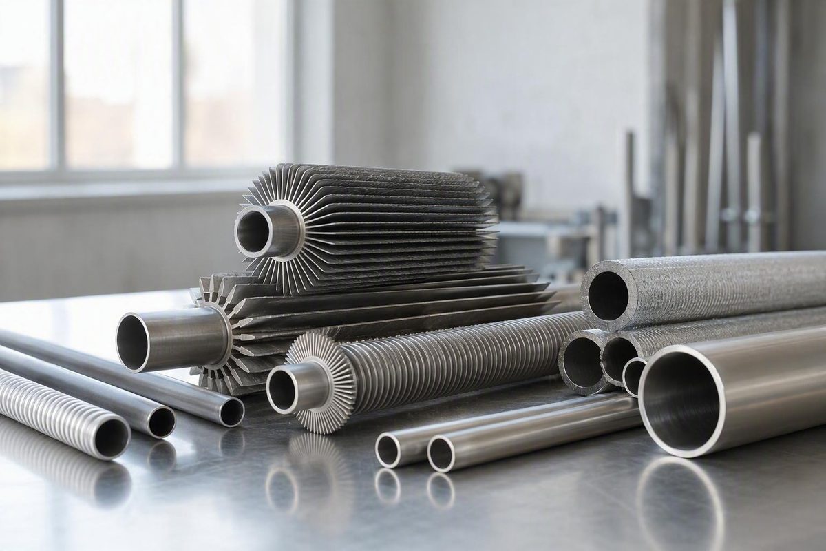
Finned tubing combines a pressure-boundary base tube with extended surface formed from the tube wall or attached to its exterior. The fins add external heat-transfer area, which is particularly useful when air or gas outside the tube is the limiting side.
Select the product as one system: define the service first, specify the base tube independently, then choose the fin material, geometry, and attachment. More area alone does not guarantee a proportional increase in heat duty.
Quick answer: what finned tubing is and when it helps
A finned tube has two functional parts:
- The base tube contains the internal fluid and forms the pressure boundary.
- The fins increase the surface exposed to the external fluid.
The extended surface may be integral—formed from the tube wall—or applied as a separate strip, sleeve, plate, or other element. Representative applications include condensers, chillers, refrigeration equipment, air-cooled heat exchangers, boilers, economizers, and waste-heat-recovery units. Fins are especially relevant when the outside medium, such as air or flue gas, has a relatively low heat-transfer coefficient (DLSS’s finned-tube selection guide).
Added area is only one part of the thermal design.
More fins are therefore not automatically better. Fin spacing must be evaluated against airflow or gas-side pressure drop, deposit accumulation, the intended cleaning method, and maintenance access. A dense fin pack that cannot be kept clean may lose the benefit that its additional surface was intended to provide.
Construction selector: integral, wrapped, embedded, extruded, brazed, or welded
The construction describes how heat passes from the base tube into the fin and how the interface may respond to temperature, thermal cycling, corrosion, vibration, handling, and cleaning. The following categories and application associations are screening guidance drawn mainly from supplier descriptions, not independent comparative testing or universal service limits (DLSS’s construction overview).
| Construction | Physical attachment | Commonly associated service | Principal concern and evidence limit |
|---|---|---|---|
| Integral low fin | Fins cold-formed from the tube wall | Compact condensers, evaporators, chillers, and coolers | Fin height and material combinations are less flexible; published ranges are supplier-specific |
| L-foot | L-shaped strip helically wrapped under tension | Moderate-temperature, cost-sensitive air service | Contact relies on winding tension; cycling and temperature limits depend on the complete design |
| LL-foot | Successive L-shaped feet overlap | Air coolers where greater tube coverage is wanted | Coverage does not prove corrosion protection or stable contact in every environment |
| KL-foot | L-style foot pressed into a knurled tube surface | Service needing stronger mechanical engagement than plain L-foot | Comparative bond strength and operating limits are process-specific |
| G-fin | Strip inserted into a groove and mechanically locked | Air coolers and mechanically demanding duties | Groove depth, minimum remaining wall, and retention must be verified for the specified product |
| Extruded bimetallic | Outer sleeve mechanically formed around the base tube | Air-cooled exchangers and exposed environments | Interface, material compatibility, and limits vary by manufacturing process |
| Brazed | Fin joined to the tube through a brazing process | Compact or elevated-temperature constructions, depending on materials | Braze alloy, process control, inspection, and service compatibility are supplier- and project-specific |
| Welded | Fin continuously joined to the tube, often helically | Boilers, economizers, air coolers, and hot-gas recovery | Weld process, examination, fatigue conditions, and acceptance criteria must be defined where required |
Integral low-fin tubing is made by displacing material from the tube wall, commonly through cold forming. Because the tube and fins are one piece, there is no separate fin-to-tube interface. The tradeoff is less freedom in fin height, profile, and material pairing than with applied fins.
The three wrapped-foot variants should not be treated as interchangeable:
- L-foot uses an L-shaped fin strip wound around the tube under tension. Thermal and mechanical contact depends on that winding tension.
- LL-foot overlaps each foot over the preceding foot, increasing coverage of the base-tube surface.
- KL-foot combines an L-style fin with knurling so that the foot is pressed into the textured surface for stronger mechanical engagement.
With G-fin, the fin strip is inserted into a groove cut into the base tube, after which the groove is mechanically closed or rolled to retain the fin.
With extruded bimetallic tubing, an outer sleeve—often made from a different material than the pressure tube—is mechanically formed around the base tube. “Extruded” should not automatically be interpreted as a metallurgical bond; the exact interface depends on the manufacturer’s process.
Brazed fins are joined through a brazing process. Fin Tube Products, for example, describes a controlled-atmosphere furnace process that creates a metallurgical joint, but that statement applies to its proprietary process rather than every brazed product (Fin Tube Products’ brazed-fin description). Welded fins are continuously joined to the tube, often as a helical solid or serrated strip.
Do not build a universal temperature ranking from catalog figures. Allowable conditions depend on the base-tube alloy, fin alloy, geometry, attachment, atmosphere, corrosion exposure, thermal cycling, and the supplier’s qualified manufacturing process.
Specify stainless as a system, not a one-word material choice
“Stainless finned tube” is incomplete because it does not identify which component is stainless. Separate the specification into three linked decisions:
- Pressure-boundary base tube: grade, product specification, manufacturing route, dimensions, condition, and required testing.
- Fin material and geometry: alloy, height, thickness, spacing, profile, and finned length.
- Attachment method: integral, wrapped, embedded, extruded, brazed, welded, or another clearly defined process.
A stainless base tube does not imply stainless fins. Supplier availability tables include carbon-steel, copper, aluminum, and stainless fins in product families that use stainless tubing, although the available combinations depend on the attachment process and dimensions (Fin Tube Products’ material and sizing tables).
Stainless may merit consideration when the internal fluid or external environment creates corrosion, oxidation, temperature, pressure, or mechanical concerns. It is not universally superior. The internal and external environments can demand different materials: the pressure tube may require one combination of corrosion resistance and mechanical properties, while the fins require another balance of conductivity, mass, cost, formability, and environmental compatibility.
Stainless fins may support material compatibility or demanding external service. Alternative fin metals can provide different conductivity, weight, cost, and manufacturing options. For dissimilar-metal combinations, review:
- Differential thermal expansion during startup, shutdown, and load changes
- Stability of fin-to-tube contact over repeated cycles
- Condensation or other electrolyte exposure
- Possible galvanic interaction
- Coatings or isolation details, where specified
- Cleaning chemistry
- Repair and replacement compatibility
The generic phrase “finned tubing” does not establish whether 304L, 316L, duplex, or another stainless grade is appropriate.
Read fin geometry without confusing area with heat duty
A usable drawing or data sheet should define:
- Tube OD: outside diameter of the unfinned base tube
- Wall thickness: pressure-boundary wall, subject to any construction-specific forming requirements
- Fin height: radial distance from the tube surface to the fin tip
- Fin thickness: thickness of the fin material
- Pitch: axial distance between corresponding points on adjacent fins
- Fins per inch: fin density, used as an alternative expression of spacing
- Fin-tip OD: maximum outside diameter across the fins
- Total length: overall end-to-end tube length
- Bare-end length: unfinned length at each end or at specified intermediate locations
Together, these variables affect external area, airflow, pressure drop, cleanability, component weight, bundle spacing, and manufacturing availability. They should not be copied individually from unrelated catalog configurations.
Area-multiplier caution
Cain Industries reports that a one-inch-OD tube with six half-inch-high fins per inch has 12 times the bare-tube external area per linear foot (Cain’s geometry example).
That is not evidence of 12 times the heat-transfer rate. Heat duty still depends on internal and external coefficients, fluid temperatures, flow, fin efficiency, contact resistance, fouling, and bundle design.
Integral low-fin tubing has distinctive geometry. DuraFin describes approximately 19 to 40 fins per inch and a fin-tip diameter that remains within the original tube OD envelope. That geometry may allow the tube to pass through a tube-sheet opening only slightly larger than the original tube diameter (DuraFin’s low-fin buyer guide). These figures describe that supplier’s general offering, not a dimensional standard.
Availability tables should be read the same way. Fin Tube Products lists one stainless-fin configuration using a one-inch-OD tube, a half-inch-high fin, a 0.020-inch fin thickness, and two through eight fins per inch (Fin Tube Products’ stainless sizing table). That entry demonstrates a stated manufacturing capability; it does not establish a preferred geometry, tolerance, attachment method, pressure rating, or industry-wide limit.
A service-first decision sequence
Use this sequence before choosing a fin construction:
- Identify the internal and external fluids. Include contaminants, solids, condensable components, and intermittent exposures.
- Establish normal and design temperatures. Record conditions for both fluids and the expected tube-metal temperature, including startup and shutdown.
- Define internal pressure. The base tube contains the internal fluid and must satisfy the applicable pressure-boundary requirements independently of the external fin choice.
- Assess corrosion and condensation. Evaluate both sides of the tube, including shutdown exposure and possible water retention.
- Assess fouling and cleaning. State the deposit type, expected severity, cleaning frequency, and intended chemical or mechanical method.
- Document vibration and thermal cycling. Include fan-induced vibration, process pulsation, transport loads, and repeated temperature changes.
- Confirm exchanger geometry and fabrication needs. Define tube-sheet interfaces, bundle spacing, supports, bends, coils, bare ends, and installation clearances.
- Compare lifecycle implications. Consider inspection, cleaning, repair, replacement, downtime, and operating penalties rather than purchase price alone.
For moderate-temperature, cost-sensitive air service, a tension-wrapped construction may be a candidate. It still requires confirmation of temperature, cycling, corrosion, and long-term contact stability. Where dissimilar materials are used, different thermal expansion rates can alter contact pressure as the assembly heats and cools.
Where cycling, vibration, handling, or mechanical cleaning is more demanding, embedded, extruded, brazed, or welded constructions may deserve evaluation. This is not a universal ranking: each introduces its own material, manufacturing, inspection, cost, and repair considerations.
For dirty external streams, start with the intended cleaning method and allowable pressure drop. Wider spacing and better access may be more valuable than maximum external area.
If the tube must be bent, coiled, or custom formed, specify the finished configuration before manufacture. Have the supplier confirm the permissible sequence, bend radius, tooling, and fin-free zones for the selected tube wall and attachment method.
Finned-tubing RFQ and purchase-order checklist
Use the following fields to prevent the supplier from having to infer the intended product. Items involving tests, qualifications, inspection records, or hold points apply only when required by the purchaser, governing documents, or approved design.
Service conditions
- [ ] Internal fluid and composition
- [ ] External fluid or gas and composition
- [ ] Normal operating temperatures
- [ ] Design temperatures
- [ ] Design pressure
- [ ] Corrosion, oxidation, or condensation exposure
- [ ] Fouling type and expected severity
- [ ] Cleaning method and frequency
- [ ] Vibration or pulsation conditions
- [ ] Expected thermal cycling
- [ ] Allowable external pressure drop, if applicable
Base tube
- [ ] Exact alloy and grade
- [ ] Applicable tubing specification and edition
- [ ] Seamless or welded requirement, if applicable
- [ ] Outside diameter
- [ ] Wall thickness and purchaser-defined tolerance
- [ ] Total length and tolerance
- [ ] Heat treatment or material condition, if required
- [ ] End preparation
- [ ] Bare-end dimensions
- [ ] Required pressure-boundary test and acceptance basis, if applicable
Fins
- [ ] Fin material and grade
- [ ] Construction or attachment method
- [ ] Fin profile: solid, serrated, low-fin, plate, or other
- [ ] Fin height
- [ ] Fin thickness
- [ ] Pitch or fins per inch
- [ ] Fin-tip outside diameter
- [ ] Finned length
- [ ] Bare-end and intermediate unfinned lengths
- [ ] Coating, cladding, or surface treatment, if required
- [ ] Permitted repairs and repair acceptance criteria, if applicable
Fabrication
- [ ] Straight, bent, coiled, or custom-formed configuration
- [ ] Bend locations, radii, tangent lengths, and orientation
- [ ] Tube-sheet or header interface dimensions
- [ ] Support and handling restrictions
- [ ] Marking requirements
- [ ] Packing, end protection, and shipping supports
Quality documentation
- [ ] Material certificates requested for the tube, fin, and joining consumables
- [ ] Required heat or lot traceability
- [ ] Dimensional inspection report, if required
- [ ] Required pressure- or leak-test records
- [ ] Specified fin-bond, braze, or weld examination and records
- [ ] Procedure or personnel qualifications required by governing documents
- [ ] Purchaser hold points and acceptance criteria
- [ ] Certificate of conformance, if required
- [ ] Approved drawing and revision identification
Do not order only “stainless finned tube.” Do not copy estimated replacement dimensions, and do not assume that a catalog size establishes the required standard. The quotation should identify proposed deviations, substitutions, and supplier assumptions.
Receiving inspection and limits of supplier data
At receipt, compare the delivered product with the purchase order and approved drawing. The inspection scope should follow the purchaser’s requirements and governing documents rather than an assumed universal regime.
- [ ] Material markings and required heat or lot traceability
- [ ] Base-tube OD, wall, and total length
- [ ] Fin height, thickness, pitch, fin-tip OD, and finned length
- [ ] Bare-end lengths and transition geometry
- [ ] Straightness and required formed dimensions
- [ ] Fin condition, spacing, and visible attachment defects
- [ ] Weld, braze, or bond condition where specified
- [ ] Dents, bent fins, corrosion, contamination, and shipping damage
- [ ] End protection and packing condition
- [ ] Required material certificates and certificate of conformance
- [ ] Specified inspection, test, and examination records
- [ ] Drawing revision and item identification
For replacements, measure the existing component and compare it with the approved equipment drawing. Do not infer tube OD or wall from a nominal pipe label, and do not assume that a visually similar catalog configuration is interchangeable.
Supplier tables establish that supplier’s stated manufacturing range, not an industry-wide standard. Published temperature values, coatings, proprietary bond descriptions, performance multipliers, and statements that code stamping is available are likewise product-specific representations. Confirm the exact configuration, materials, manufacturing process, test basis, certification scope, and purchaser acceptance requirements.
Final thermal sizing, pressure-boundary design, corrosion selection, and code compliance require project-specific engineering and the governing drawings, specifications, and code documents.
Can finned tubing be supplied in coils or custom-formed shapes?
Yes. Manufacturers list straight lengths, coils, and custom-formed configurations among their capabilities; Cain Industries, for example, describes straight lengths and fabricated subassemblies, while finned-tube manufacturers also advertise coiled products (Cain Industries’ finned-tube capabilities).
Availability does not mean that every fin attachment can tolerate every forming operation. State the finished geometry in the RFQ before manufacture, including bend radii, tangent lengths, fin-free zones, orientation, dimensional tolerances, and the intended forming sequence. Require the supplier to confirm compatibility with the selected base-tube wall, fin construction, and manufacturing process.
Are published fin-tube sizes standard across manufacturers?
No. Published tables normally describe an individual manufacturer’s available tooling and product range. They do not establish universal combinations of tube OD, wall thickness, fin height, fin thickness, pitch, attachment, material, tolerance, or operating limit.
Use catalog data to identify possible manufacturing routes, not to define the final product by default. The compact specification rule is: define the service first, specify the stainless pressure-boundary tube independently, and then add the fin material, geometry, and attachment required by the external environment. Send suppliers a complete RFQ and verify drawings, limits, certificates, tests, and acceptance requirements before treating any catalog configuration as suitable.