
What Is an EMT Set Screw Connector Used For?
It terminates EMT at a box or enclosure rather than joining conduit sections. For outdoor or wet locations, the exact connector needs express approval.
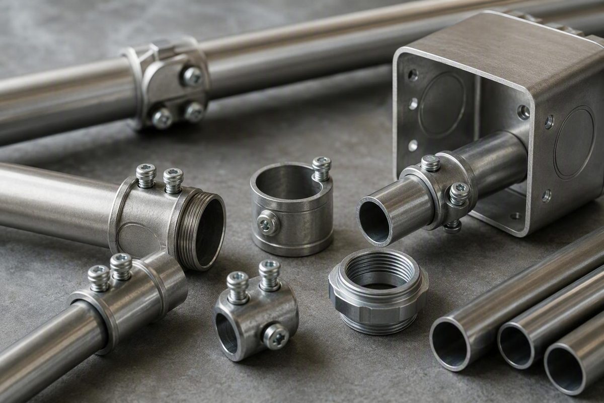
A set-screw connector is a straightforward way to terminate electrical metallic tubing at a box, panel, or enclosure. Yet “set-screw” describes only how the fitting grips the tubing. It does not, by itself, establish conduit compatibility, environmental suitability, bonding performance, or compliance with a project specification.
The correct choice starts with the connection being made: EMT to an enclosure, not conduit to conduit. From there, match the EMT trade size and enclosure entry, choose the required throat and construction, and verify the listing and instructions for the exact catalog number. This specification-first approach is especially important outside accessible, dry indoor work.
Scope note: This guide synthesizes the supplied manufacturer, distributor, retailer, and industry material. It is a product-selection framework, not an electrical-code interpretation or a substitute for model-specific installation instructions. Where code acceptance, certification, bonding, or environmental suitability is uncertain, obtain the applicable primary documentation and direction from the responsible electrical professional or authority having jurisdiction.
What an EMT set-screw connector is—and what it connects
An EMT set-screw connector is a fitting commonly used to secure electrical metallic tubing, or EMT, to an electrical box, panel, cabinet, or other enclosure. This article concerns electrical raceway fittings—not general-purpose mechanical set screws, plumbing connectors, or connectors for unspecified tubing.
The connector has two distinct interfaces:
- EMT side: The cut end of the EMT is inserted into the connector body until it reaches the fitting’s stop or otherwise seats as directed.
- Enclosure side: A threaded end passes through a compatible enclosure entry and is secured, typically with a locknut.
One or more set screws in the connector body are tightened against the wall of the EMT. The screws provide retention by bearing directly on the tubing after it has been fully inserted. Screw quantity and configuration vary by fitting and trade size.
Dry, accessible indoor use is a recurring application in the reviewed product literature. For example, Providence Pipe describes its set-screw connector as an EMT-to-enclosure fitting for dry, accessible environments and lists zinc-plated steel construction in sizes from 1/2 inch through 4 inches. Those specifications apply to that product line, not automatically to every set-screw connector. See the Providence Pipe product information.
A simplified connection looks like this:
EMT                    Connector body                   Box or enclosure
══════════════╤══════════════════════════════╤═════════│ wall
              │                              │         │
              │  seated EMT / conduit stop  │ throat  │
              │             ▲                │    ▲    │
              │             │                │    │    │
              └─────────────┴────────────────┴────┼────│
                         ▲                        │   threaded end
                         │                        │         │
                     set screw                    │      locknut
                                                  │         │
                                     conductors pass through
Simplified schematic of a typical EMT-to-box connection. Actual body shape, screw count, throat components, and locknut arrangements vary by model.
The diagram is explanatory rather than instructional. The fitting’s markings, listing, submittal documents, and installation instructions control the actual assembly.
Connector, coupling, or compression fitting: do not confuse the categories
The most important terminology distinction is between a connector and a coupling:
- A connector terminates conduit at a box, cabinet, panel, or other enclosure.
- A coupling joins one conduit section to another.
“Set-screw” and “compression” describe retention methods. They do not identify the connection being made. Both connectors and couplings can therefore be sold in set-screw or compression configurations.
A compression connector performs the same broad termination function as a set-screw connector—connecting EMT to an enclosure—but uses a compression nut and the fitting’s internal geometry rather than screws bearing directly against the tubing wall.
| Fitting | Connection made | Visible fastening method | Common selection question |
|---|---|---|---|
| Set-screw connector | EMT to box or enclosure | One or more screws in the body; threaded enclosure end and locknut | Do its size, throat, listing, and environmental approvals suit this termination? |
| Compression connector | EMT to box or enclosure | Compression nut on the conduit side; threaded enclosure end and locknut | Is the exact model approved for the required environment and entry? |
| Set-screw coupling | EMT section to EMT section | Set screws at both conduit ends | Is a straight conduit-to-conduit joint required? |
| Compression coupling | EMT section to EMT section | Compression nuts at both ends | Is the coupling compatible with the conduit and installation conditions? |
| Slip coupling | Two conduit sections where movement is constrained | Specialized sliding or adjustable arrangement | Does the work require a listed slip-coupling design? |
A slip coupling is a specialized coupling, not an enclosure connector. Eaton describes its Crouse-Hinds series set-screw slip coupling as an EMT product for electrical prefabrication and installations where conduit movement is constrained. It still joins conduit sections; it does not replace a threaded box connector. View Eaton’s slip-coupling overview.
This distinction matters when ordering. A set-screw coupling can resemble a connector in a small catalog image, but it generally lacks the connector’s threaded enclosure end and locknut arrangement. Ordering couplings when the bill of materials requires box connectors can stop installation and create avoidable returns or rework.
How to match trade size, conduit type, and enclosure entry
If the raceway is 3/4-inch EMT, begin with a 3/4-inch EMT connector.
The enclosure side deserves equal attention. Confirm:
- The type and condition of the enclosure opening
- The applicable knockout or entry arrangement
- The connector’s threaded-end dimensions and configuration
- The required locknut and throat or bushing components
- Available space inside and outside the enclosure
- Whether the completed entry must preserve a particular enclosure rating
A practical specification sequence is:
- Identify the raceway. Confirm that it is EMT rather than rigid metal conduit, intermediate metal conduit, flexible conduit, or another raceway.
- Confirm the EMT trade size. Use the project documents and raceway markings where available.
- Inspect the enclosure entry. Check the opening, wall thickness, clearance, condition, and locknut access.
- Select the connector configuration. Match trade size, throat, construction, and environmental requirements.
- Verify the catalog number. Check current manufacturer documentation and applicable certification information rather than relying on a generic category title.
Catalog breadth does not mean that every product family covers every size. Graybar’s category includes products under trade-size filters from 3/8 inch through 6 inches, together with multiple manufacturers, finishes, and throat configurations. Those filters describe the distributor’s overall category, not the range of every connector line within it. Review the Graybar category and filters.
Individual manufacturers may offer narrower ranges. American Fittings describes its steel set-screw connector and coupling line as covering 1/2 inch through 4 inches. It separately states that specified products in sizes 2-1/2 through 4 inches are approved for EMT, rigid metal conduit, and IMC. That exception is manufacturer-, product-, and size-specific; it cannot be extended to smaller sizes or competing fittings. Consult the American Fittings product documentation.
Do not assume that a connector labeled for EMT is also suitable for rigid metal conduit or IMC. Compatibility must be expressly documented for the exact fitting and size under consideration.
Packaging is a separate purchasing variable. One retail listing describes a five-pack of 1/2-inch set-screw connectors; the listing does not provide enough technical detail to establish the material, listing, throat type, or environmental approval. See the 1/2-inch pack example.
A separate Home Depot listing identifies a five-pack of 3/4-inch EMT set-screw connectors, model FECSS-75-5. This illustrates another common purchasing format, not a universal pack quantity or product recommendation. See the 3/4-inch pack example.
Compact buyer worksheet
| Field | Project requirement |
|---|---|
| Conduit type | ______ |
| EMT trade size | ______ |
| Enclosure and entry/knockout | ______ |
| Connector catalog number | ______ |
| Package quantity required | ______ |
| Listing or certification required | ______ |
| Environmental approval required | ______ |
| Project or owner standard | ______ |
Complete the catalog-number field before ordering. A description such as “3/4-inch steel set-screw connector” may still leave the throat type, finish, environmental approval, package quantity, and certification unresolved.
Materials, finishes, and insulated-throat options
Zinc-plated steel is a documented set-screw connector construction, but not every connector uses the same material or surface treatment. Distributor categories contain multiple material and finish descriptions, so construction should be verified from the exact model rather than inferred from appearance.
Keep these variables separate:
- Base material: What the body and hardware are made from
- Finish or coating: The surface treatment applied to the fitting
- Exposure: Moisture, chemicals, concrete, or other conditions the fitting will encounter
- Listing and rating: The applications for which the exact fitting has been evaluated
- Project specification: Any required material, finish, or product family
A steel body does not automatically establish wet-location suitability or adequate corrosion resistance for every environment. Conversely, another material should not be ranked as inherently better or worse without application-specific documentation. Fastening style, base material, coating, and environmental approval are related selection factors, but they are not interchangeable.
Insulated and non-insulated throats
The throat is the internal area through which conductors pass as they leave the EMT and enter the enclosure. An insulated-throat connector includes a plastic or nylon insert intended to provide a smoother surface and reduce abrasion of conductor insulation during pulling and positioning. A non-insulated connector does not contain that added insert. This manufacturer overview explains the basic insulated and non-insulated configurations.
The availability of both configurations does not establish a universal rule that an insulated throat is always required or always optional. Resolve conductor-protection requirements by checking:
- The adopted electrical code and local amendments
- Conductor and insulation details
- Raceway size and geometry
- The fitting’s listed construction
- Project drawings and specifications
- Manufacturer instructions
- Requirements imposed by the authority having jurisdiction
As a manufacturer-specific example, American Fittings describes an optional factory-installed insulated-throat bushing rated to 105°C and identifies insulated versions with a B suffix in its catalog-number system. The same documentation describes alloy-steel construction with zinc plating and a chromate finish, along with galvanized and color-coated options. These details apply only to the documented product family. See the manufacturer’s specifications.
An insulated throat may be appropriate where additional abrasion protection is specified or desired, but it does not replace proper conduit-end preparation, a compatible fitting, or any other required conductor-protection component.
Set-screw versus compression: choose by application, not reputation
Set-screw and compression connectors are both common options for terminating EMT. Neither is the universal winner.
Their basic mechanical distinction is simple:
- A set-screw connector retains EMT with one or more screws tightened against the tubing.
- A compression connector uses a compression nut and the fitting’s internal compression arrangement.
Installation access can make one style more workable than another. A set-screw connector requires driver access to each screw. A compression connector requires enough room to position and tighten its nut. Closely spaced raceways, nearby walls, enclosure geometry, and the order of assembly can therefore affect the choice.
Set-screw fittings are often characterized as quick and straightforward to install. That is useful general guidance, not measured proof that they always require less labor. Fitting size, material, tool access, installer experience, and congestion can change the result.
| Selection factor | Set-screw connector | Compression connector |
|---|---|---|
| Retention method | Screw or screws bear on the EMT wall | Compression nut tightens the fitting around the EMT |
| Tools and access | Requires driver access to each screw | Requires working space around the compression nut |
| Common dry-indoor use | Frequently associated with accessible indoor EMT work | Also used for EMT terminations, subject to product suitability |
| Environmental verification | The style name does not prove raintight, liquid-tight, or wet-location suitability | The style name does not prove raintight, liquid-tight, or wet-location suitability |
| Specification risk | May be rejected where documents prescribe compression or another construction | May be rejected where documents prescribe set-screw, steel, or another construction |
| Installation details | Screw count and tightening directions vary by model and size | Nut design and tightening directions vary by model and size |
Environmental suitability is a product-rating question. A compression nut may look more enclosed, but appearance does not establish a raintight rating. A set-screw connector likewise should not be accepted or rejected for an environment without checking the exact product documentation.
Project specifications can settle the question before field convenience is considered. An owner, engineer, facility standard, or approved submittal may prescribe a fitting style, body material, finish, throat, or manufacturer. Any proposed substitution should follow the project’s approval process.
The supplied evidence does not include independent comparative testing sufficient to conclude that one fastening style inherently provides greater strength, conductivity, fault-clearing performance, durability, or service life. Those characteristics depend on the complete fitting, its listing, and its installation—not merely on whether it has a screw or compression nut.
Dry, wet, outdoor, and concrete-tight applications
Dry, accessible interior work is the clearest recurring use case for ordinary EMT set-screw connectors in the reviewed product information. Even in that environment, the exact fitting must suit the raceway, enclosure, project requirements, and adopted rules.
Avoid two shortcuts:
- “Every set-screw connector is indoor-only.”
- “Any compression connector is suitable outdoors.”
Neither statement determines the rating of a specific catalog number.
Environmental terms describe different claims:
- General indoor suitability addresses ordinary interior conditions.
- Raintight concerns exclusion of rain under the conditions covered by the rating.
- Liquid-tight is a separate claim and is not a synonym for raintight.
- Concrete-tight concerns resistance to concrete intrusion under stated installation conditions.
- Corrosion-resistant concerns material or coating performance but does not independently establish a wet-location rating.
A marketplace listing for one steel set-screw connector represents it as intended for indoor use and as concrete-tight when taped. Because this is a seller claim rather than an official certification record, it should trigger verification of the manufacturer’s documentation for the exact product rather than be generalized to other fittings. See the listing and its stated qualification.
Where documentation says “concrete-tight when taped,” the words when taped are part of the stated condition. Use additional materials only when the exact fitting’s listing or instructions require or permit them, and follow the specified method.
A practical environmental decision tree is:
- Dry, accessible interior - Verify a connector identified for the EMT termination and installation conditions.
- Outdoor or wet location - Select an exact fitting expressly evaluated for the applicable condition and enclosure entry.
- Concrete encasement or exposure - Verify the concrete-tight claim and comply with every stated installation condition.
- Corrosive or otherwise demanding environment - Evaluate material, finish, enclosure requirements, exposure, and product approval together.
- Unclear or mixed condition - Stop and obtain product documentation or direction from the designer, qualified electrical professional, or authority having jurisdiction.
Never extrapolate environmental suitability from appearance, fastening method, retailer category, body material, or a different model in the same family.
Listings, code, bonding, and project requirements
Product acceptability should be treated as a set of concurrent requirements, not a simple hierarchy in which one document automatically overrides all others. Verify:
- The exact product markings and listing information
- The manufacturer’s current instructions and technical documents
- The adopted electrical code and local amendments
- Project drawings, specifications, and approved submittals
- Acceptance or interpretation by the authority having jurisdiction
A fitting must satisfy the requirements applicable to the installation. If the documents conflict—for example, if a generic product description appears permissive but the project specification requires another construction—the conflict must be resolved rather than choosing whichever source seems more convenient.
A retailer title containing the word “listed” is not enough by itself. Confirm the manufacturer, catalog number, size, construction, certification record, and conditions of use. Visually similar products may differ in throat configuration, conduit compatibility, environmental rating, or approved installation method.
Informal forum participants have described listed set-screw EMT fittings as generally acceptable while also noting that job specifications or local requirements may call for compression fittings. The discussion provides no controlling code citation and is not an official interpretation, so it should be treated only as anecdotal industry context. Read the discussion and its limitations.
Accordingly, the fitting name alone cannot establish compliance for a particular installation. The result can depend on the adopted code edition, local amendments, occupancy, environment, enclosure, exact product listing, and installation method.
Manufacturer documentation may identify standards associated with a product family. One reviewed manufacturer references UL 514B, NEMA FB1, and CSA C22.2 No. 18F for its steel set-screw fittings. Those references are product-family statements, not proof that every set-screw connector carries the same certification. The exact catalog number should be checked against current manufacturer documentation and, where required, the certification organization’s record.
Bonding requires the same model-specific discipline. Do not infer that the presence of a metal body or set screw, by itself, proves the adequacy of a completed grounding or bonding path. Questions involving bonding, grounding, special occupancies, uncertain certification, or conflicting documents should be referred to the responsible electrical professional or authority having jurisdiction.
Installation and purchasing checklist
Begin with an electrically safe work condition. A general conduit overview can help explain why compatible fittings and proper preparation matter, but it is not authorization to perform energized work or a substitute for the exact connector instructions. J.O. Mory’s introductory guide discusses compatible fittings, preparation, and general installation safety.
A bounded conceptual sequence for a typical connector is:
- Confirm that the fitting, EMT, enclosure entry, locknut, and any throat components are compatible.
- Prepare the EMT end as required for full seating, removing burrs and sharp edges.
- Insert the connector’s threaded end through the enclosure entry.
- Install and secure the supplied or specified locknut and any required throat component.
- Insert the EMT fully until it seats as directed.
- Orient the screw or screws so they remain accessible.
- Tighten them according to the exact manufacturer’s instructions.
- Verify seating, retention, required raceway support, and resolved bonding requirements before conductors are installed or the system is energized.
An incompletely seated or insufficiently tightened connection may not provide the intended retention. Excessive tightening may deform the EMT wall. The reviewed material does not support one universal torque value for every brand, model, screw configuration, and trade size, so use the tightening method or torque specified for the exact fitting. This fitting overview cautions against overtightening because excessive force can deform EMT.
Pre-purchase checklist
- [ ] Raceway confirmed as EMT rather than another conduit type
- [ ] Connector trade size matches the EMT trade size
- [ ] Threaded end and locknut suit the enclosure entry
- [ ] Enclosure opening is correct and undamaged
- [ ] Body material is identified
- [ ] Finish or coating is identified
- [ ] Insulated or non-insulated throat has been selected
- [ ] Required indoor, wet, outdoor, or concrete-tight approval is documented
- [ ] Conduit compatibility is expressly stated
- [ ] Listing, markings, and certification information have been checked
- [ ] Project specification permits the fitting style and construction
- [ ] Package quantity matches the takeoff
- [ ] Exact manufacturer and catalog number are recorded
Pre-installation checklist
- [ ] Connector body, threads, screws, and locknut are undamaged
- [ ] EMT end is prepared as specified for full seating
- [ ] Burrs and sharp edges have been removed
- [ ] Required throat insert or bushing is present and undamaged
- [ ] Correct locknut and associated components are available
- [ ] EMT can seat fully in the connector
- [ ] Screw orientation permits tool access
- [ ] Manufacturer tightening or torque instructions are available
- [ ] Conduit support and fastening provisions have been resolved
- [ ] Environmental installation conditions can be followed
- [ ] Bonding and continuity requirements have been resolved
Prices, inventory, customer ratings, seller descriptions, and package quantities can change.
Stop and verify before buying or installing if:
- Product markings are missing or illegible.
- Wet- or outdoor-location suitability is uncertain.
- Concrete-tight use is claimed without clear installation conditions.
- The fitting is proposed for rigid conduit or IMC without express approval.
- Tightening or torque instructions cannot be obtained.
- Product documentation conflicts with the project specification.
- The package and catalog number do not agree.
- Grounding or bonding adequacy is uncertain.
Frequently asked questions
What is the difference between a set-screw connector and a set-screw coupling?
A set-screw connector terminates EMT at a box, panel, cabinet, or other enclosure. It commonly has a threaded enclosure end secured with a locknut.
A set-screw coupling joins two sections of EMT. It receives conduit at both ends and uses set screws to retain each section. Although both fittings use screws against the tubing, they make different connections and are not interchangeable.
Are set-screw connectors allowed by the NEC?
The supplied evidence does not include a controlling NEC provision or official interpretation that supports a blanket yes-or-no answer for every installation. Informal industry participants generally describe listed set-screw EMT fittings as acceptable while acknowledging that job specifications or local requirements may demand another construction, but that commentary is not a legal determination. See the cited industry discussion.
Verify the adopted code edition, local amendments, exact product listing, installation conditions, project specification, and authority-having-jurisdiction requirements. Do not treat the words “set-screw connector” as proof of compliance.
Can an EMT set-screw connector be used outdoors or in a wet location?
Only when the exact connector is expressly approved for the applicable environment and installed according to its instructions. The term “set-screw” does not establish a wet-location, raintight, or liquid-tight rating.
Changing to a compression connector does not automatically resolve the issue. General fitting guidance likewise warns that not every compression fitting is raintight, so the model-specific rating still must be checked. See Zoro’s EMT fitting overview.
Evaluate the connector, enclosure entry, required sealing arrangement, corrosion exposure, and certification documentation as a complete system.
When should I choose an insulated-throat set-screw connector?
Choose an insulated-throat connector when the applicable project documents, fitting design, conductor and raceway details, manufacturer instructions, or adopted requirements call for it. It may also be selected where an added smooth insert is desired to reduce abrasion of conductor insulation as conductors pass through the throat.
The existence of insulated and non-insulated models does not establish a universal rule. Confirm whether the insert is required, optional, or supplemented by another listed component for the particular installation.
How tight should the set screw be?
Tighten it according to the manufacturer’s instructions for the exact connector model, trade size, and screw configuration. Seat the EMT fully before tightening. Insufficient tightening may leave the connection insecure, while excessive tightening may deform the tubing.
Do not apply a generic torque value to every set-screw connector. If the required tightening method or torque information is unavailable, stop and obtain current documentation for the catalog number before proceeding.
Ultimately, specify the connection first: an EMT-to-enclosure termination. Match the EMT trade size and enclosure entry, choose the required throat, material, and finish, and verify the exact catalog number for the conduit type and environment. Set-screw versus compression is only one decision; manufacturer instructions, project documents, adopted requirements, and the authority having jurisdiction remain controlling.