
Stainless Steel Camlock Fittings: Types, Sizes and Limits
Identify camlock types A–F, separate coupling size from hose and tube dimensions, and check stainless grade, gasket and assembly pressure limits.
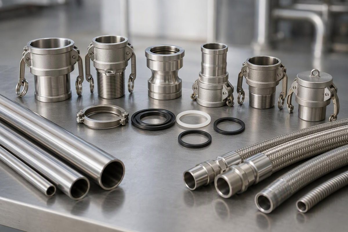
Specify stainless steel camlock fittings by cam-and-groove size, adapter or coupler, opposite-end connection, stainless grade, gasket and working conditions. “2-inch stainless camlock” is not a complete description: it does not identify the thread, hose attachment, seal or pressure limit.
The connection joins a grooved male adapter to a female coupler carrying cam arms and a gasket. Closing the arms compresses the gasket between the two parts. The cam connection’s gender is separate from the gender of any pipe thread on the other end. Dixon’s assembly procedure explains the sealing mechanism.
Camlock types A–F
These common configurations identify both ends. NPT describes the threaded versions in this table; do not assume an unidentified threaded fitting is NPT.
| Type | Cam-and-groove end | Opposite end | Typical connection task |
|---|---|---|---|
| A | Male adapter | Female NPT | Add an adapter to a male-threaded outlet |
| B | Female coupler with arms | Male NPT | Add a coupler to a female-threaded port |
| C | Female coupler with arms | Hose shank | Put a coupler on a hose |
| D | Female coupler with arms | Female NPT | Add a coupler to a male-threaded outlet |
| E | Male adapter | Hose shank | Put an adapter on a hose |
| F | Male adapter | Male NPT | Add an adapter to a female-threaded port |
| DC | Female dust cap | Closed end | Cover an unused adapter |
| DP | Male dust plug | Closed end | Cover an unused coupler |
Source: Dixon’s configuration chart, page 4. Dust caps and dust plugs are not pressure closures; both Dixon and OPW prohibit their use in pressure applications.
Types A, E and F can mate with a compatible B, C or D coupler. The letters describe the end configuration—not a requirement to pair particular letters.
Keep coupling size, hose size and tube dimensions separate
Record the size of each end independently. Dixon’s ordering example 4030-C means a 4-inch coupler × 3-inch hose shank, not a 4-inch hose fitting. Equal-size fittings often use only one size designation, which can hide this distinction. Dixon’s ordering system puts the cam end first for these unequal-size fittings.
For an existing installation, check:
- Cam end: manufacturer, series, nominal size and mating-profile dimensions against its drawing.
- Threaded end: nominal size, male or female, and thread standard. Use the NPT size identification guide when the thread is uncertain.
- Hose end: required hose ID, actual hose OD, hose construction and approved shank/retention combination.
- Weld end: actual tube OD and wall, or pipe NPS and schedule, plus weld preparation.
A nominal camlock size is not a measurement of the fitting’s outside diameter or proof of its bore. Nor does it establish compatibility with stainless tubing. Dixon separately catalogs socket-weld pipe ends, butt-weld pipe ends and weld-to-tube ends designed for sanitary tubing. Select the exact end geometry rather than welding a general-purpose hose fitting to tube. See Dixon’s weld connections, pages 67–69.
Interchangeability also has limits. Dixon states that its Dixon, Boss-Lock and EZ Boss-Lock families interchange with products made to A-A-59326D, but identifies 1/2-inch, 5-inch and 8-inch as exceptions without an interchange standard. Its Vent-Lock series requires matching L-style fittings. That mating-face compatibility does not extend to arbitrary replacement handles, shanks or crimp ferrules. Dixon’s specifications and component restrictions distinguish these cases.
Stainless grade and gasket are separate selections
Ask for the exact body grade and any required material certificate—not simply “stainless.” Dixon’s catalog includes 316 stainless cam-and-groove products, but 316 is not universally corrosion-proof. The British Stainless Steel Association warns that 316 can suffer pitting and crevice corrosion in seawater, with stagnant conditions and temperature affecting suitability. BSSA’s seawater guidance is particularly relevant when a “marine-grade” label is being treated as approval for saltwater transfer.
Select the gasket for the actual fluid, concentration, temperature and cleaning exposure. Identify its part number and construction: nitrile/Buna-N, EPDM, FKM, silicone and PTFE-based designs are not interchangeable specifications.
A seal change can limit the connection rating. Dixon’s 2023 catalog lists a 125 psi gasket pressure limit for its encapsulated designs in 3/4–4-inch sizes at 70°F (21°C). This does not raise a fitting or assembly with a lower rating to 125 psi. The catalog also notes that PTFE gasket designs require greater closing force. Gasket colors are manufacturer-specific and should not identify an unknown seal. Dixon’s gasket guidance, pages 74–77.
Do not assign one pressure rating to all stainless camlocks
As a manufacturer-specific example, Dixon’s 2023 catalog gives this general maximum-working-pressure table for its Dixon, Boss-Lock and EZ Boss-Lock couplers and adapters:
| Nominal size | Listed working pressure |
|---|---|
| 3/4–2 in. | 250 psi |
| 3 in. | 125 psi |
| 4 in. | 100 psi |
These values assume mating Dixon fittings, a standard nitrile gasket and 70°F (21°C). The catalog lists different values for some King Crimp ferrule assemblies and heavy-duty products, and requires consultation for elevated temperatures or unusual conditions. They are examples, not a universal stainless-camlock rating. Verify the current rating of the exact coupling, gasket, hose and attachment system. Dixon pressure table and product ratings.
Do not use ordinary cam-and-groove couplings for compressed air or steam. Dixon explicitly prohibits those services. If product release during disconnection is unacceptable, specify a suitable dry-disconnect system rather than assuming a locking cam arm stops flow; OPW distinguishes quick disconnects from valved dry disconnects.
Before ordering—and before connecting
Include these fields on the purchase request:
- Cam-end size, type, manufacturer/series and mating fitting identification.
- Opposite-end size and connection standard.
- Body grade, gasket part number and certification requirements.
- Fluid and concentration; operating temperature; maximum working pressure, including surges; any vacuum duty.
- Hose specification and approved retention system, or tube/pipe dimensions and weld-end drawing.
- Locking arrangement and any spill-control requirement.
Before service, inspect the sealing faces, gasket recess, adapter groove, arms, pins and locks. Dixon’s inspection procedure rejects damaged sealing surfaces and excessively worn adapter grooves; it does not treat a new gasket as a repair for damaged metal.
Close the arms fully and evenly using hand force only, then engage the specified locks. Do not hammer reluctant arms shut. Confirm that all pressure has been removed before disconnecting. These are explicit requirements in Dixon’s connection procedure.