
Socket Weld Flange: Socket Geometry, Pipe Fit and Selection
Understand socket weld flange geometry, pipe OD versus bore, preweld clearance, and when stainless service calls for a weld-neck connection instead.
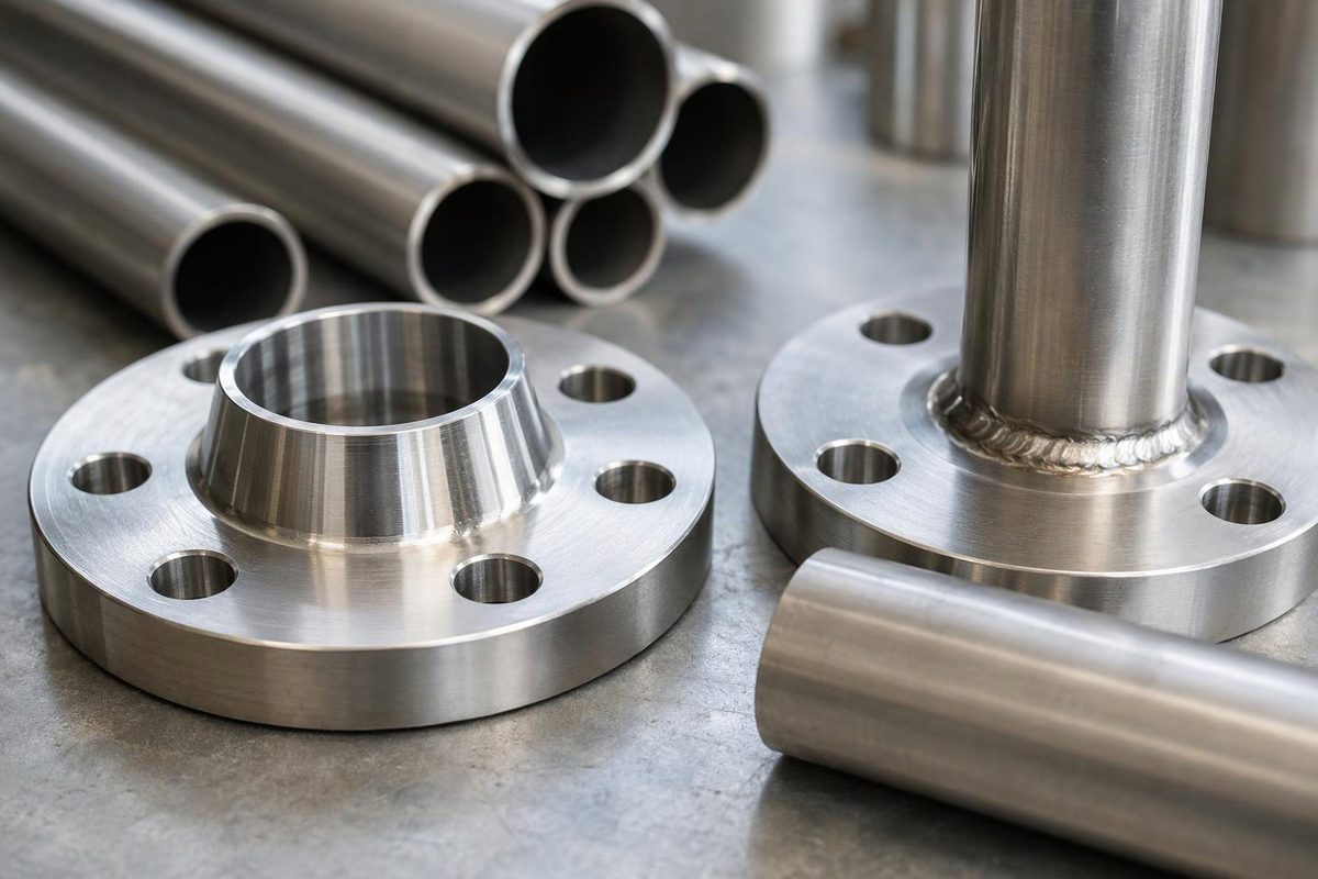
A socket weld flange receives the pipe end in a recessed socket and attaches to it with an external fillet weld. The socket has a shoulder: unlike a slip-on flange, the pipe does not pass freely through the flange. This geometry suits small-bore piping, but it also leaves an internal crevice that matters in stainless service. Wermac’s flange-type reference illustrates the joint and its single external weld.
Match the socket to pipe outside diameter, and specify the through-bore to suit pipe inside diameter. Neither dimension is simply the nominal pipe size.
What the socket dimensions mean
Read the supplier’s sectional drawing rather than relying on the word “bore.” A socket weld flange has several separate dimensions:
- Socket bore or counterbore: the larger opening that receives the pipe OD.
- Socket depth: the axial distance from the socket entrance to its shoulder.
- Through-bore: the smaller flow opening beyond the shoulder, selected to suit the connecting pipe wall or schedule.
- Bottom clearance: the axial space between the pipe end and socket shoulder at fit-up. It is not the clearance around the pipe OD.
Drawing letters vary by supplier. Shaw Stainless calls the through-bore B1 and the socket bore B2; its chart explicitly distinguishes both from socket depth. Shaw’s dimensional data provides this example:
| Measurement for an NPS 1 connection | Dimension, in. | What it identifies |
|---|---|---|
| Pipe nominal OD | 1.315 | Outside of the connecting pipe |
| Schedule 40S pipe nominal wall | 0.133 | Pipe wall thickness |
| Schedule 40S pipe nominal ID | 1.049 | Pipe flow opening |
| Shaw Class 150 socket bore B2, minimum | 1.36 | Recess receiving the pipe |
| Shaw Class 150 standard through-bore B1 | 1.05 | Flow opening beyond the shoulder |
| Shaw Class 150 socket depth | 0.50 | Depth before allowing for bottom clearance |
Pipe values are from Penn Stainless’s pipe-dimension chart; flange values are Shaw’s catalog dimensions, not a complete manufacturing-tolerance specification or a universal drawing.
The practical distinction: NPS 1 pipe is not 1.000-in.-OD tubing. A flange socket intended for 1.315-in.-OD pipe is not automatically suitable for 1-in.-OD tube. Also, changing from Schedule 40S to 80S keeps this pipe OD at 1.315 in. but changes nominal ID to 0.957 in. State the pipe schedule when selecting the flange through-bore, even though the pipe still enters the same nominal-size socket. For more pipe values, use the Schedule 40S stainless pipe guide.
Fit-up: socket depth is not insertion depth
Do not assume the pipe should remain hard against the shoulder during welding. Wermac’s assembly reference quotes ASME B31.1-1998: insert the pipe fully, then withdraw it approximately 1/16 in. (1.6 mm) before welding. It explains that bottom clearance helps reduce residual stress at the weld root during weld-metal solidification. That historical quotation is not a substitute for the project’s governing requirements. Socket weld assembly reference
For fabrication, use the project’s governing code edition, approved welding procedure and joint detail to establish the actual clearance and weld dimensions. Check the clearance and engagement before welding; the external fillet does not show where the pipe end sits inside the socket. The bottom-clearance dimension is not a fillet-weld size.
When to use it—and when to reconsider
Socket weld flanges were developed for smaller, high-pressure pipe connections. Their socket assists alignment, while the external fillet-weld arrangement avoids a pipe-to-flange butt-weld joint. Shaw lists stainless examples in Classes 150 and 300, so “socket weld” does not itself designate a pressure rating. Shaw product and application data
Two service questions deserve particular attention:
- Can the wetted joint tolerate a crevice? The pipe-to-socket recess can create corrosion problems in stainless systems carrying corrosive products. Where that recess is unacceptable, consider a properly specified butt-welded weld-neck flange instead. This removes the socket recess; it does not establish the cleanability or corrosion suitability of the entire flanged assembly. Wermac’s socket weld limitations and weld-neck geometry
- Will vibration or repeated bending govern? Socket weld fatigue performance depends on weld geometry, toe and root condition, and loading—not just flange class. An EPRI-sponsored vibration-fatigue study, focused on small-bore connections in nuclear power plants, examined these factors and compared socket welds with butt-welded weld-neck specimens. Treat vibrating small-bore connections as an engineering selection issue rather than a routine flange substitution. Vibration fatigue testing study
Specify the pipe-side connection explicitly
Before ordering, identify socket weld, NPS, connecting pipe OD and schedule, required through-bore, and the supplier’s socket bore/depth drawing. Then confirm that the project permits this joint geometry and defines its fit-up, welding and examination requirements.
Keep those pipe-side checks separate from flange material, class, facing, gasket and bolting selection. ASME B16.5 covers flange dimensions, tolerances and pressure–temperature ratings; it is used alongside the applicable piping code, not instead of it. ASME B16.5 scope The broader stainless flange buying checklist covers those flange-side specification fields.