
What Does a Transition Coupling Connect?
It bridges pipe or conduit ends that differ in material, actual OD, size or joint system. A snug fit alone proves neither pressure nor burial approval.
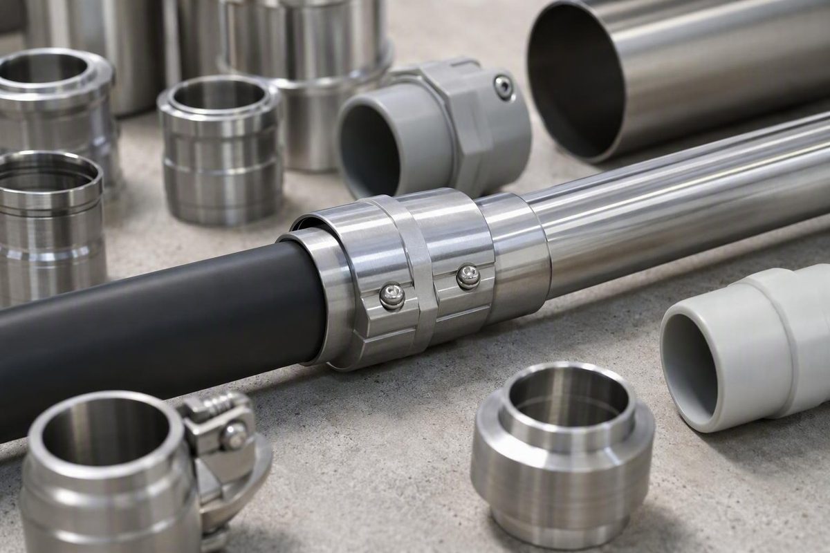
A transition coupling joins two pipe or conduit ends that differ in material, actual outside diameter, nominal size, pipe class, wall system, or connection method. Selecting one is a two-sided specification task: identify and measure both ends, define the service, and verify the exact coupling model—not merely the brand, nominal size, or product-category label.
The essential rule is:
Physical fit is not proof of pressure capacity, burial approval, axial restraint, fluid compatibility, listing, or code acceptance.
Use current product data and installation instructions to verify every critical characteristic. If the documentation does not answer an essential question, stop rather than treating an apparently snug connection as suitable.
What a transition coupling is—and what the term does not guarantee
A transition coupling is a fitting used where the two connected ends differ in one or more ways:
- Pipe or conduit material
- Actual outside diameter, or OD
- Nominal pipe size
- Pipe schedule, class, SDR, or dimension ratio
- Wall thickness or stiffness
- Joint system
- End configuration
Common applications include cast iron to plastic drainage pipe, ductile iron to HDPE or PVC pressure pipe, HDPE to steel, PVC to steel, copper to plastic, and transitions between conduit systems.
“Transition coupling” describes the fitting’s function, not a universal construction. One product may use an elastomeric sleeve, metal shield, and clamp bands. Another may use compression glands, locking teeth, an electrofusion end, a grooved housing, threads, or a welded transition. These mechanisms are not interchangeable.
Catalog terminology can also be broad. A transition category may contain true couplings alongside adapter nipples, terminal adapters, threaded fittings, mechanical-joint adapters, and other products that change the connection at one end. For example, Victaulic’s transition category includes several coupling families as well as a PVC adapter nipple. Identify how each end connects rather than inferring the mechanism from the category name.
Related products include:
-
Standard coupling: Normally connects compatible ends within the same dimensional or joint system.
-
Reducing coupling: Directly connects different pipe sizes, often while maintaining their centerline.
- Adapter: Changes an end connection—for example, from plain pipe to a thread, flange, groove, socket, or mechanical joint.
- Reducer: Uses a separate fitting body to change line size.
- Transition coupling: Accommodates a difference in material, OD, class, size, or joint system between its two sides.
One product can fit more than one definition. Dresser describes Style 62 as a reducing and transition coupling for changes in pipe size, outside diameter, or class, demonstrating why exact geometry matters more than the category label (Dresser Style 62 overview).
Most importantly, a coupling that slips over both pipes has demonstrated only possible insertion. It has not demonstrated suitability for pressure, potable water, burial, corrosive soil, concealed installation, axial loading, fire protection, or the conveyed medium.
Start with the service, not the coupling catalog
Do not begin by searching for a phrase such as “4-inch PVC-to-steel coupling.” First classify the system. The service determines which coupling families can be considered.
First-pass decision tree
| Service branch | Questions to settle before product comparison |
|---|---|
| Gravity drainage, waste, soil, or vent | Is the joint above ground or buried, exposed or concealed? What materials and actual ODs are present? Is a shielded design required? What testing and local plumbing requirements apply? |
| Pressurized water or sewer | What are the working, surge, and test pressures? What temperature range applies? How will thrust and axial movement be restrained? Is the line buried, exposed, or subject to settlement? |
| Potable water | Is the exact model and size approved for potable-water contact? Are all wetted components—including the gasket, lubricant, and coating—acceptable? |
| Electrical or telecom conduit | Which conduit materials, dimensional systems, and end connections are being joined? Must the joint resist pull, water entry, burial, encasement, or connection loads at an enclosure? Which model-specific listings or project requirements apply? |
| Industrial process service | What fluid and concentration are involved? What pressure, temperature, cleaning regime, external atmosphere, and corrosion exposure apply? Is electrical isolation required? |
| Fire-protection piping | Which system and adopted code edition govern? Is the fitting listed for the exact use? Does the location involve pump suction, seismic restraint, or another application-specific condition? |
For every branch, record:
- Conveyed fluid, cable, or conduit service
- Normal working pressure
- Surge and test pressure, if applicable
- Minimum and maximum operating temperature
- Above-ground or buried location
- Exposed, concealed, encased, or inaccessible installation
- Soil, atmospheric, chemical, or stray-current exposure
- Expected vibration, settlement, thermal movement, and axial loading
- Project specifications and jurisdictional requirements
- Inspection, testing, and documentation requirements
A shielded elastomeric coupling sold for sewage, drain, and soil work should not be assumed suitable for a pressurized main. Nor does above-ground use establish burial suitability. PexUniverse describes the displayed Mission Band-Seal range for sewage, drain, and soil applications and states that it is listed for above-ground use; that retailer description is not evidence of universal pressure or underground approval.
Manufacturers maintain different transition families because different systems require different mechanisms. In the supplied Victaulic category information, potable-water use is expressly identified for Styles 856 and 644; that statement should not be projected onto every other listed style.
Tensile loading is another dividing line. A connection used during directional-drilling pullback, or anywhere the pipe may be pulled axially, needs an explicit allowable pullout or tensile specification. Compression sealing or push-lock engagement alone does not prove pullback suitability. Distributor guidance similarly warns against using ordinary compression or push-lock products for directional-drilling loads unless manufacturer pullout specifications permit it (transition-coupling selection guidance).
Stop for qualified design review when the service is high-pressure, municipal, industrial, hazardous, or life-safety related. Confirm the product, joint design, restraint, installation, and testing against the governing specification and requirements of the authority having jurisdiction.
Size both sides by actual outside diameter
Nominal pipe size is a system designation. It does not promise that every material carrying that designation has the same outside diameter.
A coupling therefore requires two independent checks:
- Does pipe A fall within side A’s accepted OD range?
- Does pipe B fall within side B’s accepted OD range?
Build a two-sided pipe record
Before ordering, record the following for each pipe:
| Field | Pipe A | Pipe B |
|---|---|---|
| Material | ||
| Nominal size | ||
| Measured actual OD | ||
| Pipe standard or dimensional system | ||
| Schedule, class, SDR, or dimension ratio | ||
| Wall thickness | ||
| Inside diameter, if wall support may be needed | ||
| End or joint type | ||
| Coating or lining | ||
| Roundness and surface condition | ||
| Existing or new pipe |
Compare each pipe with the correct coupling side
A coupling schedule may state:
- Side A accepted OD: minimum X to maximum Y
- Side B accepted OD: minimum M to maximum N
Each measured OD must fall within the range for its designated side. Do not average the measurements, reverse an asymmetric fitting unless the instructions permit it, or assume an out-of-range pipe can be accommodated with additional torque.
Confirm that the range also applies to the pipe material and wall system. Two pipes can share an OD but respond differently to clamping when one has a rigid iron wall and the other is flexible thermoplastic.
Measure existing pipe correctly
Take readings within the intended sealing area and away from bells, weld beads, grooves, flares, and damaged ends. Determine whether any permanent coating is included in the specified fit, and remove only deposits or scale that the approved preparation procedure permits removing.
Compare the results with the coupling manufacturer’s ovality limits and field-measurement instructions.
Inspect for pits, gouges, seams, ridges, wall loss, and other conditions that could interfere with sealing or make the existing pipe unsuitable for continued service.
Unknown pipe may need to be safely exposed and positively identified before selection. McWane Ductile advises checking each pipe against the corresponding coupling-side OD range and notes that unusual existing steel, concrete-pressure, asbestos-cement, or other pipe can require a custom coupling after its type, size, OD, and—where possible—manufacturer are identified (McWane Ductile connection guidance).
Worked same-nominal-size example
Consider nominal 3-inch cast-iron drainpipe joined to nominal 3-inch plastic pipe. PexUniverse’s retailer table lists 3-inch cast iron at 3.350 inches OD, plastic or steel at 3.500 inches OD, and copper at 3.125 inches OD. These are illustrations from that retailer’s category data, not universal dimensions; verify the applicable pipe standard, actual field dimensions, and exact coupling schedule. In the cast-iron-to-plastic example, the listed OD difference is 0.150 inch (Mission transition-coupling category).
The correct candidate is a transition design whose cast-iron side accepts the measured cast-iron OD and whose plastic side accepts the measured plastic OD. The catalog’s material labels must still be confirmed against the actual pipe standards and conditions.
Compare the main transition-coupling designs
Shielded elastomeric drainage couplings
A typical shielded drainage transition uses an elastomeric sleeve or gasket, a continuous metal shield, and clamp bands.
This is a common arrangement, not a universal definition. Pressure rating, burial status, required shielding, torque, and permitted location must come from the exact model documentation.
Mechanical compression and step couplings
Mechanical compression couplings use gaskets compressed against the pipe by glands, end rings, bolts, or similar hardware. A step coupling has different receiving diameters for dissimilar ODs. Some reducing designs also join different nominal sizes or pipe classes.
Check pressure, temperature, pipe-end gap, allowable deflection, wall-support requirements, and restraint instead of assuming all bolted couplings perform alike.
Locking couplings
Locking designs add teeth, grippers, or other elements intended to resist axial movement. The grip mechanism must be approved for each pipe material. Hardware designed to engage ductile iron or steel may damage, distort, or inadequately grip plastic.
The word “locking” is not a substitute for an allowable axial-load or pullout rating for the actual pipe, size, wall system, pressure, and installation.
Push-to-connect fittings
Push fittings use internal seals and retention components, sometimes with material-specific pipe support. Compatibility is end-specific. The cited SharkBite guidance uses collar colors to distinguish fittings for designated CTS tubing, PVC, and polybutylene, and warns that insertion alone does not make an unsupported material pairing secure or warrantied (push-to-connect transition guidance).
Do not remove, substitute, or improvise an internal liner unless the manufacturer expressly permits it.
Electrofusion transitions
An electrofusion transition generally fuses to HDPE on one side and connects through threads, a flange, a metal end, or another mechanical system on the other. Fusion preparation, equipment, operator requirements, cooling time, pressure rating, and dimensional compatibility remain product-specific.
Threaded, grooved, weld-end, and mechanical-joint transitions
HDPE-to-steel and other transitions may be available with:
- Male or female threaded ends
- Machine-grooved ends
- Weld ends
- Flanges
- Mechanical-joint adapters
- Purpose-built coupling bodies
For conduit, verify both end systems rather than ordering by material names alone. Determine whether the product connects directly to another conduit, terminates at an enclosure, or changes to a thread, groove, flange, or other interface. Pull resistance, water-entry protection, burial or encasement suitability, and any required listing must be established for the exact model. A supplier category demonstrates the breadth of HDPE, steel, PVC, threaded, grooved, weld-end, terminal-adapter, and mechanical-joint products, but cannot establish the rating or approval of any individual item (transition and conduit catalog).
Design comparison
| Mechanism | Typical transition task | Flexible or rigid? | Support or restraint questions | Documentation to check |
|---|---|---|---|---|
| Shielded elastomeric | Cast iron to plastic drainage | Usually flexible | Does the shield provide stabilization only? Is separate anchoring required? | OD ranges, location, listing, torque, test method |
| Mechanical compression | Dissimilar pressure-pipe ODs or classes | Varies | Is wall support required? Is the joint restrained? | Pressure, temperature, gasket, torque, deflection |
| Step coupling | Two specifically different ODs | Varies | Could the smaller or softer pipe deform? | OD range for each end, material and wall limits |
| Locking coupling | Transition requiring axial grip | Usually semi-rigid or rigid | Are grippers approved for both materials and expected loads? | Pullout rating, wall range, pressure, installation |
| Push-to-connect | Repair between approved plumbing materials | Generally rigid at fitting | Does each end have the correct liner and retainer? | Materials, insertion depth, location restrictions |
| Electrofusion transition | HDPE to another connection system | Rigid at transition | How is the non-HDPE side restrained? | Fusion procedure, pressure, cooling, operator requirements |
| Threaded transition | Plastic or PE to threaded equipment or metal pipe | Rigid | Are thread loads isolated from plastic? | Thread standard, sealant rules, pressure, torque |
| Grooved transition | Grooved steel, plastic, HDPE, or special ends | Style-dependent | Are groove and housing details material-specific? | Groove dimensions, gasket, pressure, movement |
| Weld-end fitting | HDPE or another system to welded steel | Rigid | How are heat and alignment controlled? | Joining procedure, material grade, inspection |
| Mechanical-joint adapter | DI-system connection to HDPE, PVC, or another OD system | Usually rigid | Is a stiffener, transition gasket, or separate restraint required? | OD system, gasket, stiffener, torque, restraint |
Choose by material pairing and pipe behavior
Material names narrow the field, but they do not complete the specification. The same material may be manufactured in multiple OD and wall systems, and each pipe responds differently to clamping, thrust, temperature, and corrosion.
| Material pairing | Common design direction | Main verification points |
|---|---|---|
| Cast iron to PVC or ABS | Fully shielded elastomeric drainage transition | Both ODs, permitted location, shielding, torque, drainage limitations |
| Ductile iron to HDPE | Mechanical coupling, MJ adapter, or purpose-built transition | HDPE stiffener, gasket, SDR, pressure, material-specific restraint |
| Ductile iron to PVC or steel | Transition coupling or approved MJ arrangement | OD system, wall support, pressure, restraint |
| HDPE to steel | Electrofusion/metal transition, threaded, grooved, weld-end, MJ, or dedicated coupling | HDPE dimension ratio, joining procedure, restraint, pressure |
| PVC to steel | Step or flexible transition | Sealing width, controlled torque, PVC support, pressure, movement |
| Copper or CTS tubing to plastic | Material-specific adapter or push fitting | Exact tubing system, liner, end designation, temperature, location |
| Stainless steel to carbon steel | Mechanical, flanged, threaded, or welded transition with corrosion controls | Galvanic exposure, coatings, isolation, gasket, bonding or grounding requirements |
Cast iron to PVC or ABS drainage
A fully shielded elastomeric transition may accommodate the OD difference between cast iron and plastic drainage pipe. Select both sides by actual OD and confirm whether the exact model is permitted above ground, underground, exposed, or concealed.
Do not infer pressure capacity from the metal shield. A shield can stabilize the assembly without converting a gravity-drainage fitting into a pressure-rated joint.
Ductile iron to HDPE
This pairing combines relatively rigid ductile iron with flexible polyethylene. Depending on the approved design, the HDPE side may require:
- An internal stiffener matched to the pipe’s inside diameter and wall system
- An HDPE mechanical-joint adapter
- A transition gasket
- A broad compression surface
- Material-specific axial restraint
The two sides may need different restraint hardware. A restraint approved for ductile iron should not automatically be used on HDPE.
Ductile iron to PVC or steel
Determine whether the non-ductile pipe uses ductile-iron-size OD, iron-pipe-size OD, or another system. Some approved mechanical-joint arrangements use a transition gasket to accommodate an OD difference, but that does not make such a gasket universal.
Check pressure, surge, pipe class, wall support, and restraint on both sides.
PVC to steel
A step or flexible coupling can bridge differences in OD and stiffness. Because PVC can deform under concentrated or excessive clamping, the selected design may require a broad sealing surface and controlled torque. Verify pressure, temperature, support, and restraint for the exact PVC schedule or class.
HDPE to steel
The pairing name alone does not select the joint. Possible configurations include threaded transitions, grooved ends, weld-end steel transitions, mechanical-joint adapters, electrofusion products, and dedicated mechanical couplings. Selection depends on the HDPE OD and dimension ratio, steel end configuration, pressure, joining procedure, and expected axial load.
Copper, PEX, CPVC, PVC, and legacy plastics
Each end must be approved for the exact material and dimensional system. “Plastic” is not a sufficient specification. PEX, CPVC, PVC, PE-RT, HDPE, and polybutylene can differ in OD, ID, stiffness, temperature limits, and support requirements.
A fitting that accepts copper or CTS tubing on one end may require a different liner, collar, socket, or joining process on the other. Follow the end-specific insertion, curing, cooling, and accessibility requirements.
Stainless steel to carbon steel or copper to galvanized steel
Dissimilar metals in a conductive environment can form a galvanic couple and may accelerate attack on the less noble material. An approved insulating gasket, boot, union, spool, or coated coupling may form part of the corrosion-control strategy.
Electrical isolation is not a complete corrosion remedy. The design may also need to address coating damage, crevices, soil or fluid conductivity, stray current, water chemistry, external moisture, bonding, and grounding requirements. General plumbing guidance likewise identifies direct copper-to-galvanized connections as a galvanic-corrosion concern and presents a dielectric union as one possible transition method (dissimilar-pipe overview).
Select the gasket compound for the conveyed medium, temperature, and external environment. EPDM, NBR, FKM, and neoprene appear in transition-product literature, but those names do not constitute a universal fluid-compatibility chart. Confirm the exact formulation with the manufacturer.
Check sealing, pipe support, and axial restraint separately
A sound connection raises four separate performance questions.
1. What forms the seal?
The seal may be formed by:
- An elastomeric sleeve compressed by clamps
- End gaskets compressed by glands or bolts
- An O-ring
- A fused HDPE interface
- A solvent-cemented socket
- Threads with an approved sealing method
- A grooved gasket compressed by a housing
A watertight seal at rest does not establish performance under pressure cycling, thrust, vibration, settlement, or thermal movement.
2. What shields or stabilizes the joint?
Check the allowed deflection and movement. Do not assume that a product described as flexible can accommodate unlimited offset.
3. What supports the pipe wall?
HDPE and some thin-wall plastic or composite pipes can deform under gasket or clamp pressure. An internal stiffener may be required to preserve roundness and provide a reaction surface.
The stiffener must correspond to the pipe’s inside diameter, wall thickness, or dimension ratio. The requirement is product- and pipe-specific.
4. What resists axial movement?
Resistance may come from:
- An integral locking mechanism
- Material-specific restraint glands
- Thrust blocks
- Anchors
- Harnesses or tie rods
- Restrained joints elsewhere in the system
- Structural supports
A compression seal alone is not proof of pullout resistance. Restraint components must also be approved for the material they grip.
Torque is product-specific
Use the exact model’s value, tightening sequence, and specified tool.
PexUniverse states a maximum of 60 in-lb for the Mission Band-Seal range it describes and recommends a preset calibrated torque wrench. This is retailer-stated guidance for that identified range only; it must not be transferred to another product (Mission Band-Seal retailer guidance).
The joint specification should separately address:
- Pressure thrust
- Vibration and cyclic loading
- Thermal expansion and contraction
- Differential settlement
- Angular deflection
- Maximum pipe-end gap
- Tensile or pullout load
- Support and anchoring
- Corrosion protection
Exact allowable values must come from current documentation for the selected model and size.
Install to the selected product’s instructions
Installation methods vary, but a disciplined workflow reveals common selection and workmanship problems before the system enters service.
Pre-installation checklist
- Positively identify both pipe materials.
- Confirm nominal sizes and dimensional standards.
- Measure both actual ODs in the sealing zones.
- Check ovality using the manufacturer-approved method.
- Inspect for corrosion, scale, cracks, gouges, coatings, seams, and wall loss.
- Confirm schedule, class, SDR, dimension ratio, or wall thickness.
- Verify side A and side B orientation.
- Confirm gasket compatibility with the fluid and temperature.
- Verify working, surge, and test-pressure requirements.
- Confirm above-ground, burial, exposed, concealed, and encased-use status.
- Identify internal-stiffener requirements.
- Identify axial-restraint and anchoring requirements.
- Confirm torque, engagement depth, pipe-end gap, and testing procedure.
- Match the model, size, components, and instructions to the approved submittal.
Prepare the pipe ends
Make cuts appropriate to the selected joint. Remove debris and damaging burrs without reducing the sealing surface below the accepted OD. Protect that surface from scratches, gouges, weld spatter, and contaminants.
Align the pipes so the coupling is not forced to correct an offset beyond its documented allowance. Observe the required insertion or engagement depth.
Some shielded drainage couplings contain a central internal stop and are not slip couplings. They cannot necessarily be moved completely onto one pipe and then slid back over the joint. Inspect the product geometry and plan the cut length and assembly sequence before positioning the pipes.
Assemble and tighten
Seat both pipe ends as instructed and maintain the required end gap. Confirm that the coupling is not twisted and that shields, glands, bolts, retainers, or clamps are correctly positioned.
Tighten in the manufacturer-specified sequence and stages. Use a calibrated torque wrench or preset tool where instructed. Do not tighten by feel, particularly on plastic pipe.
Do not add sealant, lubricant, cement, pipe dope, or other chemicals unless the exact instructions call for them. The retailer guidance for the cited Mission Band-Seal range says not to use sealant or chemicals; that direction must not be generalized to products whose instructions require an approved lubricant or sealant.
Support and test the assembly
After assembly:
- Inspect for full seating, alignment, even compression, displaced gaskets, abnormal housing gaps, and pipe deformation.
- Verify and record final torque where required.
- Confirm that stiffeners, restraints, anchors, and supports are installed.
- Perform the manufacturer- or project-specified leak, water, or pressure test.
- Reinspect after testing for movement, telescoping, leakage, and distortion.
Troubleshooting transition-coupling problems
| Symptom | Likely issue | Corrective action |
|---|---|---|
| Coupling will not fit one end | Wrong side, wrong OD range, coating buildup, oval pipe | Stop; remeasure and verify the model, orientation, and pipe condition |
| Leakage after tightening | Wrong OD, damaged gasket, poor surface, misalignment, uneven torque | Follow the applicable site safety procedure, dismantle as authorized, inspect, and correct the cause |
| Plastic pipe becomes oval | Excessive torque, concentrated loading, missing stiffener, incompatible design | Replace damaged components and use the specified support and torque |
| Pipe does not reach its engagement mark | Debris, burr, incorrect cut length, internal stop, misalignment | Remove and prepare the end correctly; do not compensate with extra torque |
| One pipe telescopes into the other | Missing stop, washer, support, or restraint | Install the specified anti-telescoping provision or select another design |
| Joint pulls apart | The coupling seals but is not restrained | Redesign the restraint and verify allowable axial load |
| Persistent leak at a pit or seam | Unsuitable sealing surface | Move the joint to sound pipe or use an approved repair or engineered solution |
| Clamp or bolt damage | Excess torque, wrong tool, cross-threading, incompatible hardware | Replace damaged parts and follow the specified sequence |
| Joint moves after testing | Inadequate support, anchoring, or settlement control | Correct the external support system rather than adding torque |
| Gasket extrudes or rolls | Wrong size, poor insertion, excessive gap, incompatible assembly | Install the correct components according to the instructions |
Never improvise work on an active pressure joint. Follow the applicable site safety, isolation, authorization, and selected-product procedures before inspection or dismantling.
Verify ratings, approvals, and terminology before ordering
A complete purchase description should identify the exact product and every condition it must satisfy.
Procurement checklist
Confirm the following in current model-specific documentation:
- Manufacturer, family, exact model, size, and part number
- Transition pairing
- Accepted OD range for side A
- Accepted OD range for side B
- Nominal-size labeling
- Approved pipe materials
- Schedule, class, SDR, or dimension-ratio limits
- Required wall thickness or inside diameter
- Internal-stiffener requirements
- Gasket compound and medium compatibility
- Working-pressure rating
- Surge and test-pressure limits
- Operating-temperature range
- Axial-restraint status and allowable load
- Angular deflection and pipe-end gap
- Torque and tightening sequence
- Insertion or engagement depth
- Lubricant, sealant, and surface-preparation requirements
- Support and anchoring requirements
- Leak or pressure-test procedure
Also verify the permitted location and service:
- Above ground
- Buried
- Exposed
- Concealed
- Encased
- Potable water
- Drainage, waste, or soil
- Sanitary or storm sewer
- Electrical or telecom conduit
- Industrial process
- Fire protection
Treat standards and listings as application-specific
A distributor-authored article associates ASTM C1173 with certain underground flexible transition couplings and ASTM C1460 with certain above-ground shielded couplings. These secondary-source references are orientation points only—not proof that either standard governs every transition. Verify the current standard’s scope, exact product listing, project specification, and adopted jurisdictional requirements (secondary standards orientation).
Apply the same caution to NSF, UL, AWWA, and similar designations. A designation in a title, image description, or category filter does not establish that every size, gasket, configuration, and use has the same approval. Obtain current model-specific documentation.
Do not confuse couplings and reducers
A transition coupling bridges incompatible pipe ends. A reducing coupling changes size directly at the joint. A concentric reducer changes size through a separate body while generally maintaining the centerline. An eccentric reducer offsets the centerline to maintain a selected outside elevation or address application-specific alignment.
There is no universal flat-side-up or flat-side-down rule for eccentric reducers. Orientation depends on the system geometry and direction of supply.
Fire-pump suction piping is an important stop condition. Secondary fire-protection guidance reports application-specific eccentric reducer or increaser requirements where the suction pipe and pump suction flange differ in size, including installation intended to avoid air pockets. Confirm the current adopted code and arrangement with a fire-protection professional and the authority having jurisdiction rather than substituting a generic reducing coupling (reducing and eccentric fitting comparison).
Do not rely on replacement claims alone
A retailer may describe one brand as a direct replacement for another, but equivalence requires more than similar appearance. Confirm:
- Both OD ranges
- Overall length and stop geometry
- Shield and clamp design
- Gasket material
- Torque
- Pressure and temperature ratings
- Location approval
- Listings and certifications
- Installation requirements
The safest purchasing shortcut is not a brand name or nominal-size label. It is a complete record of both pipe ends and the service between them.
Data-sheet-or-stop rule: If the exact model and size do not have verifiable OD ranges, ratings, gasket compatibility, location approval, restraint status, and installation instructions, do not specify or buy the coupling.
Frequently asked questions
Can two pipes with the same nominal size need a transition coupling?
Yes. Nominal size does not guarantee the same actual OD across cast iron, copper, steel, PVC, HDPE, and other dimensional systems. The pipes may also differ in class, wall stiffness, or joint configuration.
Measure both ODs and compare each with the accepted range for its corresponding coupling side. A standard same-size coupling may fit one pipe but fail to compress correctly around the other.
Can a transition coupling be used on pressurized or buried pipe?
Some can, but suitability must be stated for the exact model, size, material pairing, and installation. A gravity-drainage coupling should not be assumed suitable for pressure, and above-ground approval should not be treated as burial approval.
For pressure service, verify working, surge, and test pressure; temperature; gasket compatibility; pipe-wall support; axial restraint; and thrust control. For burial, also check external corrosion protection, settlement, installation requirements, and applicable project specifications.
Does an HDPE transition coupling require an internal stiffener or separate restraint?
It may require one, both, or neither, depending on the coupling and the HDPE pipe’s OD, inside diameter, wall thickness, and dimension ratio.
A stiffener supports the flexible pipe wall under compression. Restraint addresses axial movement and pullout. They perform different functions. Follow the pipe and coupling manufacturers’ instructions, and confirm that the restraint is approved for HDPE.
What is the difference between a transition coupling and a reducing coupling or reducer?
A transition coupling accommodates incompatible materials, ODs, classes, or joint systems. A reducing coupling primarily joins different pipe sizes directly at one joint, although some products perform both functions.
A concentric reducer generally maintains the centerline. An eccentric reducer offsets it to maintain a selected outside elevation or manage application-specific flow and air-pocket concerns. Select according to system geometry and service requirements rather than terminology alone.
What torque should be used on a shielded transition coupling?
Use only the torque specified for the exact manufacturer, model, and size. The value can vary with the clamp, shield, gasket, pipe material, and product listing.
No torque value should be transferred from a similar-looking product. Follow the specified tightening sequence and use a calibrated or preset tool where required; extra torque is not a valid remedy for wrong sizing, damaged sealing surfaces, or missing restraint.
Select from the complete two-sided record
A reliable transition begins with two pipe records and one service definition. Confirm each material, actual OD, dimensional and wall system, fluid or conduit service, pressure, temperature, location, gasket, wall support, restraint, corrosion strategy, and required approval.
Then match those facts to current documentation for the exact coupling model and size. If any essential rating or installation requirement is missing, stop the selection rather than treating physical fit as proof of suitability.