
Tri-Clamp Gaskets: Size, Material and Fit
Nominal tube OD, actual bore, gasket ID and flange OD can differ. Match each dimension, then check compound suitability, cleaning exposure and assembly limits.
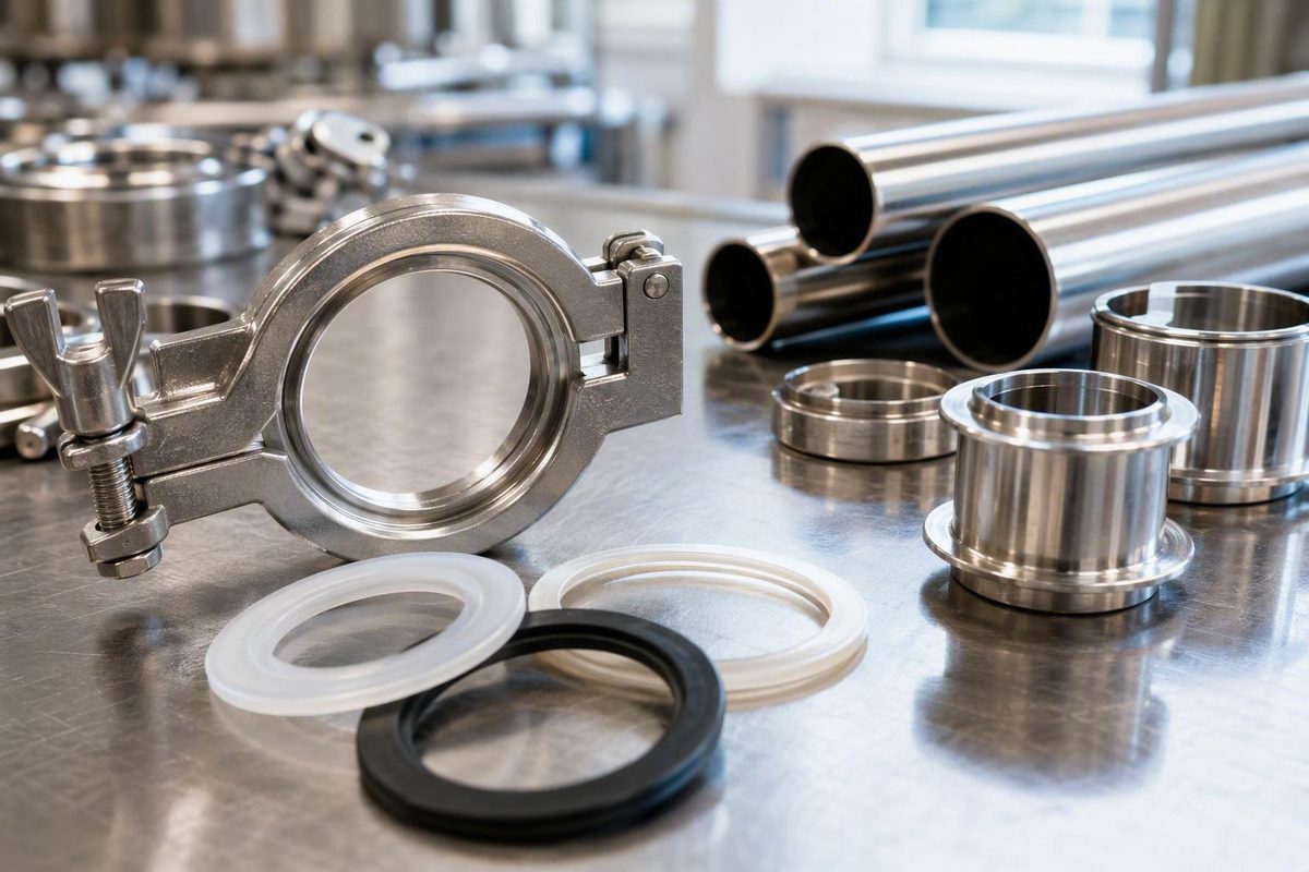
A Tri-Clamp gasket looks simple, but a reliable specification requires more than choosing a nominal size and polymer. The gasket bore must match the intended fluid path, the exact compound must tolerate production and cleaning fluids, and the gasket, ferrules, and clamp must function as a compatible assembly.
Use this sequence:
- Define the process and cleaning conditions.
- Identify the connection and every relevant dimension.
- Eliminate chemically unsuitable compounds.
- Verify temperature and mechanical behavior for the exact product.
- Select the required gasket format and clamp.
- Confirm pressure or vacuum limits for the complete assembly.
- Obtain documentation for the finished gasket, not merely the generic polymer.
Supplier guides and catalogs are useful for screening and identification. They do not replace an exact manufacturer drawing, current datasheet, certificate, validated assembly rating, or facility-specific engineering and safety procedure.
What a Tri-Clamp gasket does in a sanitary connection
A Tri-Clamp connection has three essential elements:
- Two ferrules, or flanged connection ends
- A circular gasket between the ferrule faces
- A mechanical clamp that draws the ferrules together
The gasket creates the seal. The clamp supplies and maintains the mechanical load that compresses it. Neither should be evaluated in isolation: a chemically suitable gasket may still leak if its bore is wrong, its profile does not match the ferrules, the clamp is damaged, the ferrules are misaligned, or the assembly is operated outside its documented limits.
These connections are commonly used in food, beverage, dairy, brewing, distilling, pharmaceutical, biotech, and other hygienic fluid-handling systems. Catalog terminology includes Tri-Clamp, tri clamp, triclamp, TC, sanitary gasket, and Tri-Clover. Rubber Fab associates the Tri-Clamp name with the Tri-Clover clamp used to hold the gasket, but buyers should verify the actual product specification rather than assume that similarly named parts are equivalent. Rubber Fab describes the connection’s common industries, terminology, and gasket formats.
Calling a connection “sanitary” does not make the complete installation hygienic by default. Cleanability also depends on:
- Gasket ID matching the intended flow bore
- Correct gasket centering
- Ferrule alignment
- Undamaged sealing faces
- Suitable internal surfaces
- Drainability
- The design of adjacent valves, reducers, hoses, threads, and equipment
- A cleaning method that reaches the complete fluid path
A gasket that protrudes into the bore can obstruct the fluid path. A mismatched gasket and ferrule combination can instead leave a recess where product or cleaning residue remains.
A defensible specification therefore answers six questions:
- Dimensions: What tube OD, flow bore, ferrule profile, gasket ID, gasket OD, and clamp profile are required?
- Product compatibility: Can the exact gasket compound tolerate the production fluid, including minor ingredients and expected contaminants?
- Cleaning compatibility: Can it tolerate every cleaning, sanitizing, and sterilizing fluid and cycle?
- Temperature: What are the continuous, peak, upset, and cycling temperatures?
- Mechanical conditions: What clamp, pressure, vacuum, alignment, pipe loading, and assembly procedure apply?
- Documentation: What declarations, test evidence, certificates, and traceability records are required for the finished gasket?
The phrase finished gasket matters.
Start with the operating conditions, not a favorite material
Selecting EPDM because it worked on another line—or PTFE because it has broad supplier-described chemical resistance—skips the most important step: defining the application.
Complete a worksheet before opening a catalog.
| Specification field | Information to record |
|---|---|
| Product fluid | Product name, carrier fluid, ingredients, concentrations, solids, oils, fats, alcohols, acids, and expected contaminants |
| Cleaning fluids | Every detergent, caustic, acid, sanitizer, solvent, rinse, and sterilizing medium |
| Chemical conditions | Concentration, pH where relevant, exposure duration, circulation condition, and frequency |
| Temperature | Normal continuous temperature, start-up temperature, cleaning temperature, peak temperature, and upset condition |
| Cycling | Heating and cooling pattern, cycle frequency, and whether the joint is inspected or retightened |
| Pressure | Normal, peak, surge, and test pressure |
| Vacuum | Expected level and whether it is continuous, intermittent, or produced during cooling or draining |
| Flow | Flow rate, pulsation, and sensitivity to bore restrictions |
| Assembly | How often the joint is opened, cleaned, inspected, and reassembled |
| Environment | Outdoor exposure, ozone, UV, washdown chemicals, and nearby oils or solvents |
| Tube and bore | Tube outside diameter, wall or actual flow bore, and whether unequal tubes are being joined |
| Ferrule | Connection family, profile, flange OD, face condition, and governing drawing or standard |
| Gasket | Required ID, OD, thickness or profile, format, material, and compound designation |
| Clamp | Size, design, manufacturer, hardware condition, and tightening instructions |
| Alignment | Angular or lateral offset, piping loads, flange spacing, and support condition |
| Documentation | Datasheet, material declaration, lot certificate, traceability, regulatory basis, test evidence, and change policy |
Check product and cleaning exposure separately
The production fluid and cleaning regime are separate compatibility problems. A compound may tolerate a water-based product but degrade under concentrated caustic, acid cleaner, solvent, steam, or repeated high-temperature cycling. A compound selected for aggressive cleaning chemistry may also have unsuitable mechanical behavior or inadequate process documentation.
Record concentration, temperature, and duration rather than writing only “caustic” or “steam.” An occasional peak temperature is not equivalent to continuous exposure.
Generic compatibility tables are screening tools, not application approvals. Suitability can change with:
- The precise formulation and cure system
- Chemical concentration
- Mixed chemicals
- Temperature
- Pressure
- Exposure time
- Cycling frequency
- Mechanical compression
- Product-purity or extractables requirements
Use a table to eliminate clearly unsuitable material families. Where leakage, contamination, or equipment damage would have significant consequences, obtain written guidance for the exact compound and stated conditions.
Treat published temperature ranges as leads, not guarantees
Published temperature ranges vary among suppliers and can even differ between a seller’s product entry and its general comparison table. Differences may reflect distinct formulations, service definitions, test assumptions, or inconsistent catalog information.
The governing information should be the current datasheet and instructions for the exact:
- Manufacturer
- Compound
- Gasket format
- Size
- SKU
- Operating conditions
The same principle applies to pressure and vacuum. A material’s temperature or chemical-resistance table does not establish a joint pressure rating. Catalog filters likewise show searchable attributes, not capabilities shared by every item in a category.
Define the documentation threshold early
Do not wait until receiving inspection to discover that a gasket lacks required records. Depending on the process and facility, a purchase specification may require:
- Exact manufacturer and SKU
- Proprietary or standardized compound designation
- Material or formulation declaration
- Identified food-contact regulatory basis
- Relevant biological test report or certificate
- Applicable hygienic-design documentation
- Lot or batch certificate
- Manufacturing-location or country-of-origin record
- Lot traceability
- Shelf-life and storage instructions
- Change-notification commitment
Defining these requirements before purchase reduces the risk of an undocumented “equivalent” entering approved inventory.
EPDM, Buna-N, silicone, FKM, and PTFE compared
No material is universally best. The useful question is: Which exact compound survives the product, cleaning cycle, temperature, and mechanical conditions while meeting the documentation requirements?
The following table summarizes supplier-described characteristics. It is a screening comparison, not approval for a particular process.
| Material family | General supplier-described strengths | Major cautions | Installation behavior | Verify for the exact product |
|---|---|---|---|---|
| EPDM | Common candidate for hot water, steam, mild acids or bases, weathering, and some alcohol service | Common cautions include mineral or petroleum oils, many solvents, aromatic hydrocarbons, and some fatty media | Compressible elastomer, but still vulnerable to wrong sizing, extrusion, and excessive compression | Cure system, steam cycle, cleaning concentration, alcohol level, oils or fats, temperature range, and documentation |
| Buna-N / nitrile | Common candidate for many fats, oils, fuels, greases, glycols, and hydraulic fluids | Supplier cautions include strong acids or caustics, ozone, ketones, esters, aldehydes, and chlorinated or aromatic hydrocarbons | Compressible, but swelling or softening can change sealing behavior | Full fluid blend, sanitizer, ozone exposure, temperature, cure system, additives, and documentation |
| Silicone | Flexible and commonly associated with broad-temperature or elevated-temperature service | One supplier guide describes lower durability than EPDM under harsh CIP chemistry | Flexibility does not correct bad alignment, damaged ferrules, or an incorrect profile | Cure system, tear resistance, cleaning exposure, extractables requirements, and operating limits |
| FKM / Viton | Candidate for oils, fuels, solvents, acids, and elevated temperatures | Steam and vacuum suitability varies by formulation and finished product | Elastomeric, but compression behavior must match the ferrules and clamp | Grade, concentration, steam cycle, low-temperature behavior, vacuum approval, and finished-part records |
| PTFE | Broad supplier-described chemical resistance and elevated-temperature capability | Relatively rigid and less compressible; suppliers warn about creep, cold flow, leakage during wide temperature changes, and possible clamp requirements | Requires good alignment and controlled loading; tightening harder is not a universal correction | Virgin, filled, envelope, or composite construction; clamp requirement; cycling; dimensions; pressure; and documentation |
The detailed chemical cautions and temperature values in supplier guides must be treated as product-specific screening information. Rheonics, for example, distinguishes peroxide-cured EPDM, Buna, FKM, silicone, and PTFE while warning that listed temperatures can vary by brand. Its material guide also identifies concentration- and chemistry-sensitive limitations.
EPDM
EPDM is frequently shortlisted for aqueous service, hot water, steam, mild acids or bases, and some alcohol processes. It can be a practical candidate for water-based food and beverage systems, but that reputation should not be generalized to every CIP or SIP cycle.
Common supplier cautions concern mineral and petroleum oils, solvents, aromatic hydrocarbons, and fatty media. Guidance can differ between suppliers, especially for animal or vegetable oils and high-fat products. That disagreement is a reason to identify the complete product mixture and obtain compound-specific confirmation—not to average the claims.
Buna-N or nitrile
Buna-N is commonly considered for oils, fats, fuels, greases, glycols, and hydraulic fluids. It may therefore be shortlisted when an EPDM compound is unsuitable for the production fluid.
Its limitations can become decisive during cleaning. Supplier guidance warns about substances including strong acids or caustics, ozone, ketones, esters, aldehydes, and chlorinated or aromatic hydrocarbons. The production fluid may be compatible while the sanitizer or cleaning solvent is not.
Silicone
Silicone is valued for flexibility and is widely associated with broad-temperature service. Flexibility, however, must not be treated as permission to leave ferrules misaligned or sealing faces damaged.
Eagle’s supplier guide characterizes silicone as less durable than EPDM against harsh CIP chemicals. That is a comparison to investigate for the exact compounds, concentration, temperature, and cycle—not a universal rejection of silicone. The same guide presents its material statements as general selection guidance.
FKM or Viton
FKM is commonly shortlisted for oils, fuels, solvents, acids, and elevated-temperature conditions. “Viton” is often used in catalogs, but buyers should identify the actual FKM grade or proprietary formulation rather than relying on the family or trade name.
Steam and vacuum require special care. A generic comparison may characterize FKM as useful for vacuum while the seller’s finished gaskets and fittings are expressly not vacuum-rated. That conflict illustrates the difference between a material characteristic and an approved finished assembly.
PTFE
PTFE is broadly described by suppliers as chemically resistant, relatively rigid, and less compressible than elastomers. Those characteristics can be useful chemically while making the connection less mechanically forgiving.
Suppliers identify creep and cold flow as concerns, and some warn that large temperature changes can alter sealing behavior. Clamp design, ferrule alignment, sealing-face condition, gasket format, and thermal cycling therefore require explicit review. A reinforced, filled, envelope, or composite design may behave differently from a plain PTFE gasket.
One commercial page excludes beer and wine from its general PTFE recommendation without supplying a technical basis. That unsupported exclusion should not be converted into an industry rule. Compatibility should be checked against the actual beverage, cleaning agents, temperature, process requirements, and finished gasket.
Why generic temperature limits are unreliable
A Sanitary Fittings comparison table lists Buna at −35°F to 250°F. Rheonics lists Buna at −30°F to 200°F and PTFE up to 500°F. Glacier Tanks lists PTFE up to 450°F. These figures describe different supplier tables or products; none is automatically correct for every gasket. The Sanitary Fittings product page also contains differing product-level and comparison-table values. Glacier Tanks identifies its PTFE range and its warnings about creep, cold flow, and temperature variation.
A defensible shortlisting method is:
- Eliminate compounds incompatible with the production fluid.
- Eliminate compounds incompatible with cleaning, sanitizing, or sterilizing fluids.
- Check continuous, peak, and cycling temperatures for the exact compound.
- Compare compression, creep, flexibility, extrusion, and assembly behavior.
- Confirm the required gasket format and clamp.
- Verify documentation for the finished component.
- Confirm pressure or vacuum capability for the complete assembly.
Tri-Clamp sizing: tube OD, flange OD, gasket ID, and clamp size
The most common sizing error is treating nominal Tri-Clamp size as the ferrule-flange outside diameter. Supplier sizing guides instead define nominal size by the outside diameter of the connected tubing.
The dimensions describe different features:
                           F. CLAMP SIZE
                    catalog/profile designation
                  ╭────────────────────────────╮
                  │     clamp around ferrules  │
                  ╰───────╮              ╭─────╯
                          ▼              ▼

 Tube wall ───────────╮  ╭────────────────╮  ╭─────────── Tube wall
                      │  │  C. GASKET ID  │  │
 B. FLOW BORE  ◄──────┼──┤◄──────────────►├──┼──────►
                      │  │                │  │
 Tube wall ───────────╯  ╰────────────────╯  ╰─────────── Tube wall
                         ▲                ▲
                         │   gasket OD    │
                         ◄──── D. ───────►

        ◄──────── A. NOMINAL TUBE OD ────────►
             measured across the tube exterior

                    ◄──── E. FLANGE OD ────►
                 measured across the ferrule face
- A. Nominal tube OD: Outside diameter of the connected tube
- B. Actual flow bore: Internal opening through the tube or ferrule
- C. Gasket ID: Opening through the center of the gasket
- D. Gasket OD: Outside diameter or locating profile of the gasket
- E. Flange OD: Outside diameter across the ferrule face
- F. Clamp size: Catalog designation for the corresponding clamp profile
Nominal tube OD, actual bore, gasket ID, gasket OD, flange OD, and clamp size can all be different numbers.
The shared-flange trap
Some smaller sizes share a flange and clamp profile. The following mapping is published by Glacier Tanks and should be verified against the drawing for the actual components. Its sizing guide defines nominal size by tube OD and lists the corresponding flange and clamp dimensions.
| Nominal tube OD | Approximate flange OD | Listed clamp designation |
|---|---|---|
| 1/2 in. | 0.984 in. | 3/4 in. clamp |
| 3/4 in. | 0.984 in. | 3/4 in. clamp |
| 1 in. | 1.984 in. | 1.5 in. clamp |
| 1.5 in. | 1.984 in. | 1.5 in. clamp |
| 2 in. | 2.516 in. | 2 in. clamp |
| 2.5 in. | 3.047 in. | 2.5 in. clamp |
| 3 in. | 3.579 in. | 3 in. clamp |
| 4 in. | 4.682 in. | 4 in. clamp |
Shared flange dimensions do not make the corresponding gaskets interchangeable. A gasket between two 1-inch tubes needs an opening appropriate to that fluid path; a gasket between two 1.5-inch tubes needs the larger opening. The wrong bore can produce a step, recess, or gasket intrusion even when the same clamp profile closes around both ferrules.
Catalog dimensions show why the terms cannot be substituted for one another. One listed 1.5-inch gasket has a 1.375-inch ID and 2-inch OD. The values 1.5 inches, 1.375 inches, and 2 inches describe the same listed product but refer to different features. Brewery Gaskets publishes this nominal-size, ID, and OD example.
Field-measurement workflow
When the existing part number is unknown:
- Identify the connection family. Confirm that it is the expected sanitary clamp profile rather than a visually similar connection.
- Measure the tube OD. Measure straight tubing where possible, not the ferrule flange.
- Measure the flow bore. Record the opening on both sides, especially when the connected components differ.
- Measure the flange OD. Use it as a cross-check, not as the sole ordering dimension.
- Inspect the gasket profile. Record its cross-section, locating features, flange, envelope, reinforcement, and thickness.
- Measure gasket ID and OD. Treat dimensions from a used gasket cautiously because it may be swollen, stretched, compressed, or permanently deformed.
- Record clamp markings and design. Note manufacturer, nominal marking, hinge arrangement, bolt arrangement, and part number.
- Locate the ferrule or equipment drawing. An equipment-side connection may control the required profile.
- Compare every value with the supplier drawing. Resolve discrepancies before ordering.
Do not order solely from:
- Flange OD
- Clamp appearance
- A worn gasket’s dimensions
- A marketplace title
- Color
- A remembered nominal size
- The fact that one clamp can pull two ferrules together
Inch, metric, and standard-specific connections
Industrial catalogs list inch and metric tube sizes and DN designations. A catalog’s inclusion of several measurement systems does not establish cross-standard interchangeability.
Require verified drawings for the ferrule, gasket, and clamp; do not create a cross-standard substitution from nominal size alone.
Same-size joints, unequal tubes, and gasket formats
For equal-size connections, match the gasket opening to the intended tube bore and then confirm the ferrule profile, gasket ID and OD, and clamp.
Unequal-size joints require additional review.
Directly joining compatible unequal tubes
Some smaller tube sizes share a ferrule and clamp profile and can therefore be connected physically. Glacier Tanks recommends:
- A 1.5-inch gasket when directly joining 1-inch and 1.5-inch tubes
- A 3/4-inch gasket when directly joining 1/2-inch and 3/4-inch tubes
These are supplier-specific recommendations for compatible shared-flange combinations, not a universal rule for arbitrary unequal connections. The same guide warns that direct joining creates an abrupt change in flow diameter. Its unequal-size guidance identifies both larger-gasket examples and the resulting flow transition.
A properly selected tapered reducer may be preferable where the process requires a gradual bore transition, defined orientation, drainage, or validated hygienic performance. Whether a concentric or eccentric design is appropriate is a piping-design question that should be resolved from the process requirements and governing drawings—not from gasket size alone.
Gasket formats are not interchangeable categories
Catalogs identify several gasket formats:
- Mini gaskets
- Type I gaskets
- Flanged Type II gaskets
- Schedule V gaskets
- Type III PTFE envelope gaskets with fillers
- Reinforced or composite gaskets
- Metal-detectable gaskets
These names can describe different profiles, constructions, or intended ferrule arrangements. An envelope gasket, for example, may combine a PTFE contact surface with a filler; it is not simply a solid PTFE gasket in another color.
The available evidence does not support universal rules such as “use Type II for pressure” or “use an envelope gasket for every aggressive chemical.” Select the format from:
- The mating ferrule design
- Manufacturer drawings
- Production and cleaning chemistry
- Temperature and cycling
- Clamp and loading requirements
- Validation and documentation needs
Installation without creating leaks or flow-path obstructions
Installation must follow the gasket and clamp manufacturers’ instructions and the facility’s lockout, isolation, hygiene, hazardous-fluid, and return-to-service procedures. Vendor installation guidance supports inspecting alignment and sealing surfaces, seating the gasket correctly, and controlling clamp tightening, but it does not replace the governing facility procedure. The Sanitary Fittings guide describes these assembly and inspection checks.
A general sequence is:
- Isolate the system. Stop flow and apply the required facility lockout or process-isolation procedure.
- Make the connection safe. Confirm that pressure, vacuum, hazardous contents, and harmful temperature have been removed before opening the joint.
- Inspect all components. Check ferrules, sealing faces, gasket, clamp segments, hinge, threads, pins, and fastening hardware.
- Clean the contact surfaces. Remove product, scale, fibers, old gasket material, and debris without damaging the sealing faces.
- Center the gasket. Place it evenly in the intended ferrule groove or locating profile.
- Align the ferrules. Bring them together without using the clamp to force misaligned piping into position.
- Fit the clamp evenly. Verify that its internal profile engages both ferrules correctly.
- Tighten as prescribed. Follow the instructions for the exact clamp, gasket, size, pressure, and temperature.
- Perform the required verification. Use the facility’s approved leak, pressure, vacuum, cleaning, or process check before returning the connection to service.
A gasket should remain centered and seated evenly around its circumference. It should not be pinched, twisted, folded, or displaced into the flow path.
Why more tightening is not automatically better
Excessive compression can warp or damage a gasket and push material into the pipeline. Intrusion changes the flow path and may create an edge or retained-material zone. Insufficient tightening can permit leakage or leave gaps at the joint.
There is no single torque for every Tri-Clamp connection. One vendor guide states 25 in-lb for a wingnut clamp, while other supplier instructions use qualitative hand-tightening guidance. Those instructions are not interchangeable across clamp designs, gasket materials, sizes, pressure conditions, or temperatures. The guide publishing the 25 in-lb figure also warns about both over- and undertightening.
For a multi-bolt clamp, Rheonics advises tightening uniformly and progressively rather than fully loading one bolt while others remain loose. Its installation guidance also calls for matching the gasket ID to the bore and the clamp profile to the ferrule.
Single-hinge, double-hinge, and bolted high-pressure clamps are distinct designs. Their category names do not establish a universal pressure capability. Use the documented rating and procedure for the exact clamp model, ferrules, gasket, size, temperature, and assembly.
Post-installation inspection
Before release—and again when required after thermal cycling or vibration—check for:
- Gasket intrusion into the bore
- Uneven flange spacing
- Incorrect clamp-segment seating
- A skewed or partially engaged clamp
- Visible leakage
- Movement at the joint
- Loosening after vibration
- Changes after heating and cooling
- Residue or moisture around the connection
If the system is pressure- or vacuum-critical, use the approved engineering test rather than visual inspection alone. Pressure testing and return to service must follow the facility’s applicable safety procedure.
Troubleshooting leaks, deformation, and recurring failures
A new leak should trigger inspection, not immediate extra tightening. Begin with nominal size and gasket bore. Then inspect centering, alignment, sealing faces, flange spacing, clamp condition, exposure history, and the gasket itself.
| Symptom | What to check first | Possible contributors |
|---|---|---|
| External leakage | Correct size and bore; gasket centering; clamp engagement | Debris, damaged face, insufficient or uneven load, wrong profile, misalignment, chemical degradation |
| Gasket protruding into bore | Gasket ID, centering, ferrule alignment | Wrong bore, pinching, excessive compression, softened or swollen material |
| Residue at joint | Bore continuity, recesses, seating, cleanability | Inadequate loading, damaged gasket, mismatched ferrules, poor drainage, ineffective cleaning |
| Swelling or softening | Exact compound and full exposure history | Product incompatibility, cleaning chemical, mixed chemicals, elevated temperature |
| Cracking or tearing | Age, handling, temperature, chemistry, installation | Chemical attack, thermal degradation, ozone, excessive deformation, damaged surfaces |
| Clamp repeatedly loosening | Hardware, vibration, supports, cycling | Vibration, thermal movement, worn threads or hinge, piping loads |
| Leak after heating or cooling | Temperature rating and cycle behavior | Compression change, differential movement, PTFE creep or cold flow, loss of clamp load |
| Recurring failure at one location | Alignment, supports, sealing faces, process transients | Pipe strain, vibration, damaged ferrule, wrong gasket, wrong clamp, unsuitable procedure |
A structured leak investigation
For a newly assembled joint:
- Confirm both tube sizes.
- Confirm the gasket’s nominal size, ID, OD, and profile.
- Determine whether unequal tubes were joined directly.
- Verify that the gasket is centered.
- Inspect flange spacing around the circumference.
- Check angular and lateral alignment.
- Inspect sealing faces for dents, scratches, distortion, or residue.
- Inspect clamp segments, hinge, threads, pins, and engagement.
- Look for molding defects, cuts, contamination, swelling, or permanent deformation.
- Review production and cleaning exposure.
- Review temperature, pressure, and vacuum history.
- Compare the installation with the exact manufacturer procedure.
Gasket intrusion or bulging can result from a wrong bore, misalignment, excessive compression, or a material whose dimensions or properties changed in service. Overtightening is one possible cause, but appearance alone does not prove it.
Swelling, softening, cracking, tearing, or discoloration can be consistent with chemical or thermal attack, but none provides a complete diagnosis. Compare the condition with the exact compound, product and cleaning records, temperature history, installation date, and manufacturer guidance.
PTFE deserves particular attention in cycling service. Glacier Tanks identifies creep, cold flow, and large temperature changes as potential concerns for its PTFE products. That guidance is product-specific and should not be generalized into a rating for every PTFE gasket. Supplier guidance also notes that thermal cycling can alter gasket compression and vibration can loosen clamp hardware.
Know when to stop tightening
Stop troubleshooting by additional tightening and obtain manufacturer or engineering guidance when any of the following applies:
- Significant pressure or vacuum
- Aggressive, toxic, corrosive, or high-temperature fluids
- Damaged or distorted sealing faces
- Uncertain chemical compatibility
- Repeated failure at the same joint
- Evidence of pipe strain or misalignment
- An undocumented gasket or clamp substitution
- Required pressure, vacuum, or hygienic validation
- A clamp that does not seat correctly
- Leakage that changes materially with temperature
Do not open, tighten, pressure-test, or return a hazardous system to service outside the facility’s isolation and test procedures.
The available evidence does not establish a universal gasket life or replacement interval. Inspection and replacement plans should reflect the validated process, cleaning cycles, assembly frequency, observed condition, manufacturer instructions, and facility requirements.
Compliance documents and the final buying checklist
Terms such as FDA, USP Class VI, 3-A, USDA, and CGMP should not be treated as interchangeable labels. Supplier guides commonly distinguish food-contact claims, biological testing, hygienic design, and manufacturing practices, but a catalog explanation is not an authoritative legal determination for a particular facility or product.
For purchasing due diligence:
- An FDA-related statement should identify the regulatory basis claimed for the material and intended contact condition.
- A USP Class VI claim should be supported by relevant test evidence and should not be assumed to establish unrelated chemical, mechanical, or hygienic properties.
- A 3-A claim should identify the applicable hygienic-design documentation or authorization rather than being treated as another name for food-contact suitability.
- USDA language should be checked for its specific scope and application.
- A CGMP reference concerns manufacturing practices; it is not a polymer grade or a substitute for component documentation.
Cole-Parmer’s supplier guide similarly treats FDA, USP Class VI, and 3-A as different considerations, while cautioning that actual suitability depends on the specific component and its documentation. Its descriptions are useful for purchasing orientation, not a substitute for qualified regulatory review.
A generic polymer, color, catalog category, or product title does not prove that every finished gasket has the same status. A catalog may offer filters for material, temperature, pressure, metal detectability, and regulatory attributes without making every combination available. McMaster-Carr’s gasket catalog illustrates these separate product filters.
Documentation checklist
Request records tied to the exact finished component:
- Manufacturer name
- Exact SKU and revision
- Compound designation
- Formulation or material declaration, as available
- Cure system where relevant
- Identified food-contact regulatory basis
- Biological test evidence where required
- Applicable hygienic-design documentation
- Lot or batch certificate
- Lot number and traceability route
- Country of origin where required
- Manufacturing-location information where required
- Shelf-life and storage instructions
- Certificate-retention policy
- Change-notification policy
- Information covering colorants, fillers, reinforcement, or detectable additives where relevant
Sanitary Fittings states that lot-specific certificates can be requested and that lot numbers appear on its gasket packaging. That is an example of documentation a buyer can request—not evidence that every supplier uses the same system. The seller describes those certificate and packaging practices on its gasket page.
Technical buying checklist
Before approval, confirm:
- Nominal tube OD on both sides
- Actual required flow bore
- Ferrule profile and connection standard
- Gasket ID and OD
- Gasket cross-section and format
- Exact material and compound
- Cure system where relevant
- Continuous operating temperature
- Peak and upset temperature
- Thermal-cycle expectations
- Product-fluid compatibility
- Cleaning-fluid compatibility
- Concentration and exposure duration
- Pressure requirement
- Vacuum requirement
- Complete-assembly rating
- Clamp type and model
- Tightening or torque procedure
- Alignment and piping-load condition
- Frequency of assembly and disassembly
- Required compliance and traceability records
Receiving-inspection checklist
At receipt:
- Compare the manufacturer, SKU, quantity, dimensions, and material with the purchase order.
- Match packaging and lot data to the certificates.
- Measure critical dimensions according to the inspection plan.
- Inspect for cuts, distortion, contamination, foreign material, or damaged packaging.
- Verify storage and shelf-life instructions from the manufacturer.
- Confirm that certificates apply to the received lot and finished part.
- Quarantine undocumented substitutions, including unexplained changes in color or markings.
- Preserve traceability through stores and maintenance issue.
- Record the installation location or equipment ID where required.
Catalog prices, inventory, review scores, ratings, and package quantities are dated commercial information. None proves technical suitability.
One-page decision path
Use this sequence for a new or revised specification:
- Define conditions: Product, cleaning chemistry, concentration, exposure, temperature, cycling, pressure, and vacuum.
- Identify dimensions: Tube OD, bore, flange OD, ferrule profile, gasket ID and OD, and connection system.
- Shortlist materials: Eliminate compounds incompatible with production or cleaning exposure.
- Choose the format: Select the verified Type I, flanged, envelope, reinforced, detectable, or other required construction.
- Select the clamp: Match the ferrule profile, loading method, conditions, and installation instructions.
- Verify assembly limits: Confirm temperature, pressure, vacuum, alignment, and cycling for the complete connection.
- Obtain documentation: Tie declarations, test evidence, and certificates to the exact SKU and lot.
- Install and inspect: Follow the governing procedures and perform the required process or leak check.
- Record the approved part: Preserve the gasket, clamp, documentation, and installation procedure as a controlled maintenance specification.
Nominal size, polymer name, color, or an FDA-style catalog label is not enough. Reliable selection comes from matching the dimensions, both exposure regimes, mechanical assembly, and finished-component documentation.
Frequently asked questions
Are 1-inch and 1.5-inch Tri-Clamp gaskets interchangeable because the ferrules have the same flange diameter?
No. The two tube sizes may share an approximately 1.984-inch ferrule-flange profile and the same listed clamp designation, but their bores and required gasket openings differ. Use a 1-inch gasket between two 1-inch tubes and a 1.5-inch gasket between two 1.5-inch tubes, subject to the exact manufacturer drawing.
For a direct connection between 1-inch and 1.5-inch tubes, that supplier recommends the larger 1.5-inch gasket. The resulting transition remains abrupt, so a designed reducer may be preferable when the process requires a controlled transition or validated hygienic configuration.
How tight should a Tri-Clamp gasket connection be?
Follow the procedure for the exact gasket and clamp. There is no universal torque.
Some guides use qualitative hand-tightening instructions, while one vendor states 25 in-lb for a wingnut clamp. Neither instruction should automatically be applied to another clamp design, gasket material, size, temperature, or pressure condition.
For multi-bolt clamps, load the bolts uniformly and progressively according to the manufacturer’s instructions. If the connection leaks, inspect gasket size, bore, centering, alignment, sealing faces, and clamp condition before tightening further.
Can a Tri-Clamp gasket be assigned a pressure or vacuum rating by itself?
Not reliably for system specification. Pressure and vacuum capability depend on the complete assembly: gasket, clamp, ferrules, size, temperature, alignment, hardware condition, pipe loading, and installation procedure.
A material table mentioning vacuum does not establish that the finished gasket or connection is vacuum-rated. Likewise, a catalog pressure filter does not assign that pressure to every product in the category. Require documented limits for the exact assembly and stated operating conditions.
Does an FDA, 3-A, or USP Class VI claim apply to every gasket made from that material?
No. These claims address different concepts, and their scope can depend on formulation, colorants, fillers, manufacturing controls, testing, size, or SKU.
Request the identified regulatory basis or test evidence and confirm that it applies to the finished gasket being purchased. A generic polymer description, color, catalog category, or product title is insufficient. Where the interpretation affects regulatory compliance, obtain review from qualified facility personnel rather than relying on a supplier label alone.
How often should Tri-Clamp gaskets be inspected or replaced?
There is no universal interval supported for every application. Set the schedule from the validated process, production and cleaning exposure, thermal cycling, assembly frequency, observed degradation, manufacturer guidance, and facility requirements.
Inspect sooner after process changes, unusual temperature or pressure events, repeated disassembly, vibration, chemical changes, or a leak. Replace a gasket when it is damaged, permanently deformed, chemically degraded, dimensionally unsuitable, contaminated beyond the approved cleaning method, or no longer supported by required documentation.